For the last couple of years, we have published a number of beneficial series in this forum to help contribute to the understanding of many of the standards in the manufacturing industry. In case you missed some of them, we are going to re-cap and link to the most popular today.
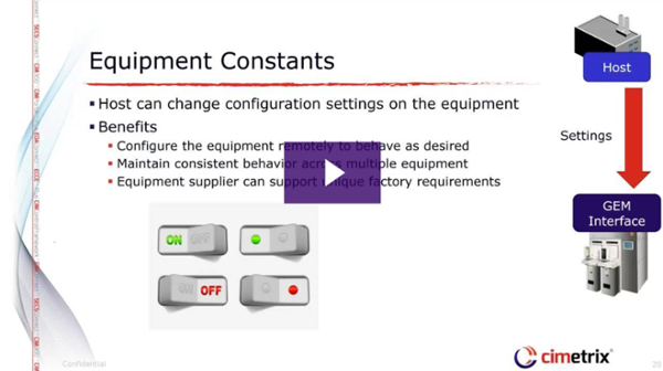
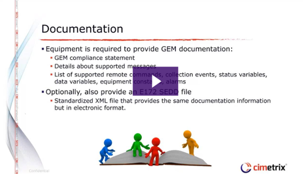
GEM Features and Benefits
This series features 15 separate posts with videos and information on some of the most important aspects of the GEM (SECS/GEM) standard. This series is one of our most popular ever and was written by a number of the Cimetrix engineering team who have studied and practiced GEM for many years.
EDA Application and Benefits in Smart Manufacturing
With the adoption of the latest SEMI EDA (Equipment Data Acquisition, also known as Interface A) standards accelerating significantly over the past 2 years, we felt it was time to highlight the applications across the industry that make the best use of these standards, and the specific manufacturing benefits that result.
Models in Smart Manufacturing
In this series, we highlighted the importance of explicit and standardized models in the context of equipment communications interfaces and some of the “smart” factory applications they support.
EDA Testing
Since the EDA/Interface A adoption process has now clearly reached critical mass, we must seriously address the question “How are we going to test the equipment and systems that incorporate these standards?” This is an excellent question, and one that has a multi-part answer, which is addressed in this 6-part series.
These, and many others including a the Cimetrix Book Club and Meet-the-Team series are some of what you can find on our blog. Be sure to subscribe today!