Industry News, Trends and Technology, and Standards Updates

Best Practices in EDA Metadata Model Design: EDA Exception Consolidation

Posted by Derek Lindsey: Product Manager on Mar 31, 2020 11:45:00 AM

You may be familiar with the brain teaser that starts, “As I was going to St. Ives, I met a man with seven wives.” As the poem continues, each wife has seven sacks, each sack has seven cats, etc. Eventually the question comes out, “How many were going to St. Ives?” The common misconception of this brain teaser is that to answer the question you must multiply all of the items together, resulting in a huge number.

Cimetrix has extensive experience in helping application developers integrate the Equipment Data Acquisition (EDA) / Interface A standards into their equipment control applications. Occasionally we encounter an equipment type that has a very large number of process modules and each process module has a very large number of exceptions. An exception in EDA Freeze II is represented by both an exception definition and an exception instance. What are the options for creating a model with a large number of exceptions?

Good

The most direct approach is to have one exception definition per exception instance as shown in the following EDA equipment model:exception-consolidation1However, with this approach, if each module has 5000 exceptions, 200 modules would result in 1 million exception instances with a corresponding 1 million exception definitions. The system resources required to deploy and maintain this model are very large.

Better

EDA allows multiple exception instances to refer to a single exception definition. The following model shows this approach:exception-consolidation2
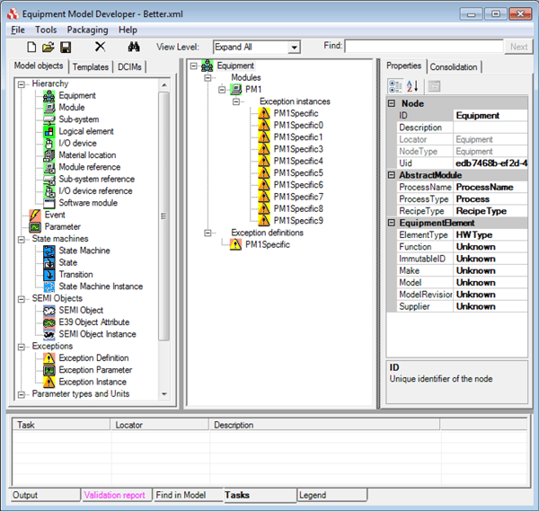
In this example, we can see that the process module has ten exception instances, but now there is only one set exception definition. Using this approach, if each module has 5000 exception instances, 200 modules would still result in 1 million exception instances, but we would now only have 200 exception definitions (one for each module). This is a significant reduction, but still quite large.

Best

The best approach for equipment with many process modules each with a large number of exceptions is to define only a few distinct exceptions per module, and then use a transient parameter (or data variable) to indicate the actual cause of the problem. The following model shows how this might look:exception-consolidation3
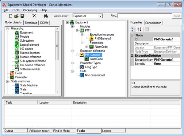
The process module in the model above only has one exception. The transient parameter AlarmCode would contain the information about what caused the exception to be triggered. It is possible to have multiple exception parameters if additional information is necessary (sub error code, description, etc.)

The EDA standards reference four exception severity levels – Information, Warning, Error, and Fatal. If we create one exception definition for each of these severities and no more than four exception instances per module, we see that a model with 200 modules would have four exception definitions and an upper limit of 800 exception instances.

This approach to exception consolidation benefits equipment makers and factories alike by reducing model complexity and model size.

The answer to the brain teaser above is that only one person was going to St. Ives – me. You don’t have to spend a lot of time and effort trying to figure out how many people, cats, etc. were in the other party, because they were travelling in the opposite direction! Similarly, if you consolidate your exception handling in EDA, you don’t have to spend a lot of time and system resources trying to handle too many exceptions.

Topics: Industry Highlights, EDA/Interface A, Doing Business with Cimetrix, EDA Best Practices

Cached Data: A New Feature in EDA Freeze 3

Posted by Brian Rubow: Director of Solutions Engineering on Jan 22, 2020 11:15:00 AM

Background

Several years ago, I was working with a client implementing EDA who wanted to collect data at higher than typical rates using the EDA trace data collection feature (essentially periodic data polling). The typical EDA data collection rate I was used to was 10 Hz, with a couple of clients implementing 20 Hz or even 40 Hz. This client, however, wanted to collect data at about 1000 Hz. This was a lot faster than we normally could accomplish, especially since the software timers and clock functionality in Windows are really designed for about 15 ms intervals. Therefore, the normal means of implementing the data collection was not going to work very well.

With a little creative thinking, I came up with a solution. Instead of using trace data collection, I decided to try event data collection. Every 1 second, I triggered an event notification and provided 1000 data samples with the event that had been collected at 1 ms intervals and stored. The 1000 samples were presented to the EDA client as an array of data, which EDA supports directly, and this solution worked very well. I also found that this approach used surprisingly few resources to implement and transmit, largely because the data is so compact. It was also very reliable.

Although this event with array data solution worked in this very specific situation, there were a few drawbacks. First of all, the client could not choose the data collection interval. Normally with trace data collection the client chooses the data collection rate to meet the needs of a specific data collection application. Secondly, the client receiving the data had to know what the data meant. The client application software had to be programmed to understand that each value in the 1000 sample array represented data collected every 1 ms. Finally, I could not use the trace start trigger and stop trigger to automatically enable and disable the reporting of the data collected. Normally, trace data collection can be started and stopped automatically to collect data between specific equipment events, which is a nice feature to focus data collection between specific processing steps or other meaningful activities.

EDA Freeze 3

A couple of years ago, the SEMI North America DDA (Diagnostics and Data Acquisition) task force, which I co-lead, decided to begin work on the next version of the EDA standards suite, commonly referred to as EDA Freeze 3. As part of this work, I raised an issue that I wanted our task force to address. That is, I wanted to be able to collect data using the EDA standard at higher frequencies than the typical 10 Hz available using today’s trace data collection. In particular, I wanted to leverage what I had learned using the event data array solution to report data collection at 1000 Hz and faster, and make this an integral part of the EDA standard without the limitations of my current solution. This new feature is now called Cached Data.

Cached Data Features

The basic principle behind this new feature is simple. First, allow the EDA client to define a Cached Data Request and specify the reporting frequency, data collection frequency, and other attributes like the number of samples, a start trigger, a stop trigger, and whether or not the triggers are cyclical. Then have the EDA server report the data for each parameter as a compact data array.

For example, an EDA client might ask for a parameter at a collection interval of 0.1 ms (10 KHz) and a reporting interval of 1 second. The result would be a set of Cached Data Reports that look like this:

EDA-Freeze-3-1-1

The equipment would collect the data every 0.1 ms and store the values for 1 second, and then send the Cached Data Report with the collected values in a tightly packed array. The EDA client would receive the data once per second and would know the data collection frequency.

Limitations

There are some limitations to the Cached Data proposal. For example, this type of data array reporting is only practical for some data types like integers, floats, Booleans and bytes. This type of data reporting is not practical for structured data or strings. Moreover, not all data can or should be collected at such high rates. Collecting data at these high rates requires robust software specifically designed for high-speed data collection. Therefore, the EDA proposal includes a way for parameter metadata to specify where the cached data feature can be used, and includes the specific minimum and maximum data collection frequencies. Therefore, the Cached Data feature is expected to be used for a limited subset of the available parameters for which the EDA server is specifically designed to provide such high-speed data collection.

gRPC & Protocol Buffers

The proposed EDA Freeze 3 standards also include the use of gRPC and Protocol Buffer technology, thereby moving EDA away from SOAP/XML over HTTP. gRPC with Protocol Buffers is a solution for a binary interface. Prelimiary test results reported to the DDA task force show dramatic throughput improvements and reduced bandwidth requirements for EDA. Additionally, the testing confirmed that reporting data in compact arrays is far more efficient for transmitting large amounts of data. In other words, the Cached Data feature is expected be even more effective due to this EDA protocol change.

SEMI Voting

Soon a new voting cycle for SEMI standards will begin where we vote on new versions of the standard. The Cached Data feature is included in two SEMI ballots: ballot 6553, a major revision of the SEMI E134 SPECIFICATION FOR DATA COLLECTION MANAGEMENT, and ballot 6527, a major revision of the SEMI E125 SPECIFICATION FOR EQUIPMENT SELF DESCRIPTION. Both are planned for voting in SEMI voting cycle 2 in 2020. Task force members are currently reviewing the latest revision of the proposed ballots.
Studies have already shown vast improvements in factory applications when collecting data at 10 Hz instead of 1 Hz. The increased performance of EDA Freeze 3 will allow the industry to dramatically improve manufacturing processes even more when data can be collected and reported at rates of 1000 Hz, 10 KHz, and beyond.

Topics: Industry Highlights, Semiconductor Industry, EDA/Interface A, EDA Best Practices

EDA Programmatic Model Building

Posted by Derek Lindsey: Product Manager on Nov 27, 2019 11:00:00 AM

The Cimetrix CIMPortalTM Plus software product allows users to achieve compliance with the SEMI Interface A standards. This includes E120, E125, E132, E134 and E164. A key element in enabling the data collection provided by Interface A is the equipment model, which has three main purposes:

  1. It defines the structure and relationships of the components that make up equipment (E120)
  2. It defines the data (parameters, events and exceptions) that are available to be used in data collection (E125)
  3. It defines the supporting structures (state machines, parameter type definitions, logical elements, etc.) for creating objects throughout the life of the running equipment (E125)eda-programmatic-model-building-pic-1

Part of the CIMPortal Plus Software Development Kit (SDK) is an application called Equipment Model Developer (EMDeveloper for short) that uses a simple drag and drop interface to allow CIMPortal Plus users to create a fully EDA-compliant equipment model. This includes making the model compliant with the E164 (Specification for EDA Common Metadata) standard which incorporates best practices from many production EDA implementations by defining common structures and other important conventions for the equipment metadata.

While EMDeveloper makes it simple to create, validate and deploy a fully compliant equipment model, there are times when equipment manufacturers want to provide a more flexible way of creating the equipment model. For example, an equipment manufacturer may offer multiple configurations of a unit of equipment with different arrangements of load ports and/or process module combinations. It is possible for the equipment supplier to save multiple equipment models that are shipped with each equipment, but this opens the door for possible human error in deploying an incorrect model file. It is also possible to create a “master model” that has all possible components defined. When the model is deployed, the equipment developer can use DisableModelNode functionality to disable the components that are not present. However, this approach may also result in errors, and is in the “gray” area of the standards (i.e., it is possible, but not encouraged).

Wouldn’t it be convenient if there was a way to create a model that exactly matched the equipment configuration?

We wouldn’t have a blog post if we didn’t already a positive answer to this question! EMDeveloper uses an API provided by the CIMPortal Plus CxModelLibrary. It does not use any sleight of hand or backdoors to create the equipment model. If a CIMPortal Plus user had the desire to do it, they could recreate EMDeveloper on their own. The API provided by CxModelLibrary allows users to programmatically create an EDA-compliant equipment model that exactly matches the desired equipment configuration.

When using programmatic model building, Cimetrix recommends first becoming familiar with the available API and determining the model building approach that works best for your equipment. The Solutions Engineering team at Cimetrix provides a sample application (including source code) that shows how to programmatically build an equipment model. This sample builds an E164-compliant model. In other words, all the expected parameters, events and exceptions and associated structures required by the standards are included as part of the resulting model.eda-programmatic-model-building-2

The EDA standards – and specifically E164 – define the types of data that are required for various components in the equipment. For example, each substrate location in the model is required to implement a SubstrateLocation state model. Moreover, this state model must appear within the equipment node in the model hierarchy that matches the physical structure of the equipment. This sample illustrates best practices in constructing model objects that can be reused based on the type of component. Programmatic model building may take a little more investment up front, but in the end, it can pay big dividends to those equipment providers that may need to change their equipment model on the fly depending on its configuration.

Once a model has been programmatically created/modified, Cimetrix also provides an API for validating the model, deploying the model to be used by an EDA client and creating an Access Control List (ACL) entry to allow a client to securely connect to the interface and gather data.

There is also a provision in the standard for addressing the concern that if the model is updated dynamically, an EDA client may have data collection plans (DCPs) that become out of sync with the modified model. In this case, the client is notified of model changes, and can also be designed to dynamically update the data collection plans based on the changes.

The Cimetrix CIMControlFramework (CCF) product makes use of this programmatic model building functionality. CCF dynamic model building is described in a blog post that you can find here.

To learn more about the EDA/Interface A standards, CIMPortal Plus or programmatic model building, click below and a Cimetrix expert will contact you. 

Topics: Industry Highlights, Semiconductor Industry, EDA/Interface A, Smart Manufacturing/Industry 4.0, EDA Best Practices

EDA Best Practices Series: Choose to Provide E164-Compliant Models

Posted by Derek Lindsey: Product Manager on Aug 28, 2019 11:42:00 AM

In the EDA Best Practices blog series, we have discussed choosing a commercial software platform, using that package to differentiate your data collection capabilities and how to choose what types of data to publish. In this post we will review why you should choose to provide an E164-compliant equipment model.

What is E164?

Equipment Data Acquisition (EDA) - also referred to as Interface A - offers semiconductor manufacturers the ability to collect a significant amount of data that is crucial to the manufacturing process. This data is represented on the equipment as a model, which is communicated to EDA clients as metadata sets. The metadata, based upon the SEMI E125 Specification for Equipment Self-Description, includes the equipment components, events, and exceptions, along with all the available data parameters.

Since the advent of the SEMI EDA standards, developers and fabs have recognized that equipment models, and the resulting metadata sets, can vary greatly. It is possible to create vastly different models for similar pieces of equipment and have both models be compliant with the EDA standards. This makes it difficult for the factories to know where to find the data they are interested in from one type of equipment to another.

Recognizing this issue, the early adopters of the EDA standards launched an initiative in to make the transition to EDA easier and ensure consistency of equipment models and metadata from equipment to equipment. This effort resulted in the E164 EDA Common Metadata standard, approved in July 2012. Another part of this initiative was the development of the Metadata Conformance Analyzer (MCA), which is a utility that tests conformance to this standard. With this specification, equipment modeling is more clearly defined and provides more consistent models between equipment suppliers. This makes it easier for EDA/Interface A users to navigate models and find the data they need.

Power of E164

The E164 standard requires strict name enforcement for events called out in the GEM300 SEMI standards. It also requires that all state machines contain all of the transitions and in the right order as those called out in the GEM300 standards. This includes state machines in E90 for substrate locations and in E157 for process management. The states and transition names in these state machines must match the names specified in the GEM300 standards.

These requirements may seem unnecessarily strict, but implementing the common metadata standard results in:

  • Consistent implementations of GEM300
  • Commonality across equipment types
  • Automation of many data collection processes
  • Less work to interpret collected data
  • Ability for true “plug and play” applications
  • Major increases in application software engineering efficiency

Knowing that a model is E164 compliant allows EDA client applications to easily and programmatically define data collection plans knowing that the compliant models must provide all of the specified data with the specified names. For example, the following application is able to track carrier arrival and slotmap information as well as movement of material through a piece of equipment and process data for that equipment.eda-best-practice-e164-1

This application will work for any GEM300 equipment that is E164 compliant. The client application developer can confidently create data collection plans for these state machines, knowing that an E164-compliant model must provide the needed state machines and data with the proscribed names.

Decide to be E164 compliant

A number of leading semiconductor manufacturers around the globe have seen the power of requiring their equipment suppliers to provide EDA/E164 on their equipment, and now require it in their purchase specifications.

If you are a semiconductor manufacturer, you should seriously consider doing the same because it will greatly simplify data collection from the equipment (and most of your candidate suppliers probably have an implementation available or underway.

If you are an equipment supplier and your factory customers have not required that your EDA models be E164 compliant, you should still seriously consider providing this capability anyway as a way to differentiate your equipment. Moveover, E164-compliant models are fully compliant with all other EDA standards. Finally, it is much easier and more cost effective to create E164-compliant models from the outset than it is to create non-compliant models and then convert to E164 when the factory requires it.

Conclusion

The purpose of the E164 specification is to encourage companies developing EDA/Interface A connections to implement a more common representation of equipment metadata. By following the E164 standard, equipment suppliers and factories can establish greater consistency from equipment to equipment and from factory to factory. That consistency will make it easier and faster for equipment suppliers to provide a consistent EDA interface, and for factories to develop EDA client applications.

Contact Us

Topics: Industry Highlights, EDA/Interface A, Doing Business with Cimetrix, Smart Manufacturing/Industry 4.0, Cimetrix Products, EDA Best Practices

EDA Best Practices Series: Specifying and Measuring Performance and Data Quality

Posted by Alan Weber: Vice President, New Product Innovations on Aug 1, 2019 12:14:00 PM

The old adage “You get what you pay for” doesn’t fully apply to equipment automation interfaces… more accurately, you get what you require, and then what you pay for!

This is especially true when considering the range of capability that may be provided with an equipment supplier’s implementation of the EDA (Equipment Data Acquisition, also known as Interface A) standards. Not only is it possible to be fully compliant with the standard while delivering an equipment metadata model that contains very little useful information, the standards themselves are also silent on the topics of Performance and Data Quality.  So you must take extra care to state these requirements and expectations in your purchase specifications if you expect the resulting interface to support the demands of your factory’s data analysis and control applications. Moreover, to the extent these requirements can be tested, you should describe the test methods and tools that you will use in the acceptance process to minimize the chance of ugly surprises when the equipment is delivered.

We have covered the importance of and process for creating robust purchase specifications in a previous posting. This post will focus specifically on aspects of Performance and Data Quality within that context.

Scope of Performance and Data Quality Requirements

From a scope standpoint, Performance and Data Quality requirements are found in a number of sections in an automation specification. The list below is just a starting point suitable for any advanced wafer fab – your needs may extend and exceed these significantly.

Here are some sample requirements that pertain to the computing platform for the EDA interface software:

  • The interface computer should have the capability of a 4-core Intel i5 or i7 or better, with processing speed of 2+ GHz, 8 GB of RAM, and 500 GB of persistent storage with at least 50% available at all times.
  • The equipment must monitor key performance parameters of the EDA computing platform such as CPU utilization (%), memory utilization (GB, %), disk utilization (GB, %) and access rate, etc. using system utilities such as Perfmon (for Windows systems) and store this history either in a log file or in some part of the equipment metadata model.
  • The network interface card must support 1 GB per second (or faster) communications.

In the area of equipment model content, the following requirements are directly related to interface performance and data quality:

  • The equipment should make the EDA computing platform performance parameters available as parameters of an E120 logical element that represents the EDA interface software itself.
  • The supplier must provide a written description of the update rates, recommended sampling intervals, normal operating ranges and behaviors, and high/low/rate-of-change limits for all key process parameters. These will be used to design data quality filters in the data path between the equipment and the consuming applications/users.
  • Equipment parameters provided through the EDA interface must exhibit a number of data quality characteristics, including, but not limited to: an internal sampling/update rate sufficient to represent the underlying signal accurately; timing of trace reports that is consistent with the sampling interval within +/- 1.0%; values in adjacent trace reports must contain then-current values at the specified sampling interval; and rejection of obvious outliers.

Advanced users of the EDA standards are now raising their expectations for the equipment to provide self-monitoring and diagnosis capability in the form of built-in data collection plans (DCPs), as expressed in some of the following requirements:

  • The supplier must provide built-in DCPs to support common equipment performance monitoring, diagnostic, and maintenance processes that are well known to the supplier. Documentation for these DCPs must define their purpose, activation conditions, interface bandwidth consumed, and the types of analysis the collected data enables.
  • The supplier must describe the operating conditions that can lead to a PerformanceWarning situation for the EDA interface.
  • The supplier must describe the algorithms used to deactivate DCPs under PerformanceWarning conditions. These might include LIFO (i.e., the last DCP activated is the first to be deactivated), decreasing order of bandwidth consumed or “size” (in terms of total # of parameters and # of trace/event requests), etc.

Because of the power and complexity of the DCP structure defined in the EDA standards, it is not sufficient to specify the raw communications performance requirement as a small number of isolated criteria, such as total bandwidth (in parameters per second) or minimum sampling interval. Rather, since the EDA interface must support a variety of data collection client demands for a wide range of production equipment, these requirements should be expressed as combinations of sampling interval, # parameters per DCP, # of simultaneously active DCPs, group size, buffering interval, response time for ad hoc “one-shot” DCPs, maximum latency of event generation after the related equipment condition occurred, consistency of timestamps in trace reports with the specified sampling interval, and perhaps others.

Moreover, some equipment types may have more stringent performance requirements than others, depending on the criticality of timely data for the consuming applications… so there may be process-specific performance requirements as well.

Measurement and Testing

Methods for measuring and testing the above requirements should also be described in the purchase specifications so the equipment suppliers can know they are being successfully addressed during the development process and can demonstrate compliance before and after shipping the equipment. Clarity at this phase saves time and expense later on.

Examples of such requirements include:

  • The supplier must test the EDA interface across the full range of performance criteria specified above and provide reports documenting the results.
  • An earlier requirement states that the EDA interface must be capable of reporting at least 2000 parameters at a sampling interval of 0.1 seconds (10Hz) with a group size of 1, for a total data collection capacity (bandwidth) of 20,000 parameters per second. In addition to this overall bandwidth capability, the supplier must demonstrate that this performance is possible over a range of specific data collection deployment strategies, meaning different #s and sizes of DCPs, different sampling intervals, group sizes, etc. without causing the EDA interface to reach one of its “Performance Warning” states or overstress its computing platform. To this end, all combinations of the following data collection configuration settings must be run for at least 15 seconds each; assuming the equipment has n processing modules:
    • Trace intervals (in seconds): 1, 0.5, 0.2, 0.1 (and 0.05 if possible)
    • # of parameters per DCP: 10, 50, 100, 250, 500, 1000 (and 2000 if possible)
    • # of DCPs: 1, 2, 3, … to n
    • Group size: 10, 5, 2, 1
  • The test client should be run on a separate computing platform with sufficient computing power to “stay ahead” of the EDA interface computer; in other words, the EDA interface should never have to wait on the client system.
  • Test reports should indicate the start and stop time of each iteration (i.e., one combination of the above settings), and verify that the timestamps of the data collection reports sent by the EDA interface are within +/- 1% of the value expected if the samples were collected exactly at the specified trace interval.
Performance parameters of the EDA interface platform should also be monitored during the tests and included in the report. These parameters should include memory usage, CPU processing load, and disk access rate (and perhaps others) for all processes that constitute the EDA interface software.

This approach is shown in tabular form for a 2-chamber tool (see below); since Group Size does not (or should not) impact the effective parameters per second rate, it is not shown in the table.edabest-measure-1
  • A summary report for all performance tests that show acceptable message generation and transmission timing across the full range of data collection test criteria must be available.
  • Detailed SOAP logs for specific performance tests must be available on request.

In Conclusion

Red_smart_factory-TW

We hope you now have some appreciation for the importance of solid requirements in this area, and can accurately assess how well your current purchase specifications express your actual needs. If you want to know more about a well-defined process for improving your specifications, or have any other questions regarding the status and outlook of the EDA standards, and how they can be implemented, please contact us.

Contact Us

Topics: Industry Highlights, EDA/Interface A, Doing Business with Cimetrix, Smart Manufacturing/Industry 4.0, Cimetrix Products, EDA Best Practices

Why choose a commercial product for the EDA (Equipment Data Acquisition) interface solution for your equipment? 为什么要为您的设备选择商用EDA解决方案?

Posted by Clare Liu (刘波); Solutions Engineer on Nov 20, 2018 11:10:00 AM
Lessons-Learned-small

Clare Liu, a Cimetrix Solutions Engineer, goes over the pros and cons of choosing a commercial product for EDA/Interface A vs. building a solution from scratch. Read it now in Chinese, or below in English. 

本文的焦点是当许多半导体设备制造商面对他们那些最先进的客户提出的自动化需求时,如何在购买支持EDA(Interface-A)标准的软件产品,或者自主开发之间做出决策。

鉴于我本人在今年初加入Cimtrix之前,曾经在一家半导体装备公司里担任EDA标准实现项目的主要开发人员,我想解释说明一下选择商业解决方案的利与弊。

1. 经验

在半导体制造设备上实现EDA要求软件开发人员具有半导体行业标准(SEMI)和半导体设备的经验。这对大多数设备供应商来说是非常困难的。即使他们已经拥有良好的软件开发人员,经验丰富的工厂自动化工程师和一个完整的硬件设计团队,他们还是需要有效的共同协作,找出如何设计一个结构良好的设备模型(SEMIE120 CEM 通用设备模型规范)并将设备所有的变量、时间和报警映射到设备模型的各个节点上(SEMI E125 EqSD设备自我描述规范)。 一个商业的EDA解决方案能够同时为OEM提供这些知识,并且可以基于该设备,提供EDA开发过程的指导方针。

2. 验收

checkmark简单地实现EDA接口功能和正确有效地实现的结果是不一样的。我从中得到的教训之一是,我们花了几乎整整一年的时间来实现EDA Freeze I的各种功能,并为测试的需要开发了客户端软件。然而,当我们将我们的EDA解决方案发布给客户工厂时,他们使用权威的第三方测试软件产品对所有设备的EDA解决方案进行了验证。我们的实现最初没有通过验收,因为我们对EDA标准的理解与客户的理解有些差异。为此我们花了很长时间来逐一解决验收中遇到的问题。商业的EDA解决方案通常已经在许多工厂得到了验证,因此更加标准化。

gantt-chart-cimetrix3. 时机

一个商业的EDA解决方案可以帮助OEM在短时间内开发出合格的EDA接口。自主开发EDA会给本已紧张的交付进度增加时间压力,如果需求来自一个新客户,第一个支持EDA标准的设备供应商通常会更有优势。在业务方面,EDA功能很有可能是获得订单的关键。在技术方面,第一个EDA的使用会成为整个Fab的范例,可以被用来制定其他设备在生产环境中必须满足的操作要求。

4.服务

使用商业EDA解决方案通常包括来自软件供应商的良好的技术支持,这些技术支持可能包含在最初的许可证费用中,或者是单独的技术支持合同。这意味着OEM公司不需要维持一个专门的软件团队来维护和解决遇到的软件问题。相反,他们可以依靠更专业的支持团队,而不用担心任何内部开发人员离开公司所带来的影响。

5. 知识更新

由于很多改进得到认同,还有很多新的技术在关键产品中的使用变得可行,半导体行业的EDA标准每年都在发生变化,在写这篇文章的时候,一个新的EDA标准冻结版本Freeze III正在投票中。商业EDA解决方案通常会紧紧追随标准的发展,同时会不断根据其他工厂用户的请求增加新的功能。这使得OEM能够快速、可靠地响应客户的最新需求。

1.成本

OEM必须为商业软件的许可证,以及可能的、每年的技术支持支付费用。

2.知识产权(IP)

一些OEM公司为了对EDA功能的源代码有完全的控制权和所有权,他们选择自主开发并拥有这些软件,其原因是大多数商业软件包通常不会为基本许可证的使用者提供源代码。

3.修复错误的时间

如果在商业软件包中发现错误,设备工程师甚至工厂客户可能需要帮助软件供应商找到根本原因。他们还必须等待供应商修复并发布新版本的软件。这对于使用者来说非常不方便。

如果您的公司正面临这样的决定,请联系我们——我们很乐意分享我们的专业知识和市场知识,并协助您做出明智的决定。

Schedule a Meeting

您可能还对以下信息感兴趣:

View Presentation: Raising the Bar
View Video: Importance of Process Module Tracking
View Video: E164 EDA Common Metadata
View Video: Equipment Modeling - E120/E125
Learn about CIMPortal 


Lessons-Learned-smallThe focus of this blog posting is the decision that many semiconductor manufacturing equipment suppliers face when deciding how to address the automation requirements of their most advanced customers, namely, whether or not to buy a commercial software package that supports the SEMI Equipment Data Acquisition (EDA / Interface A) Standards, or to develop this capability in-house.

I am especially qualified to explain the pros and cons of choosing a commercial solution, having worked as the EDA standards implementation lead developer in an equipment supplier before joining the Cimetrix team earlier this year.

  • Pros

1. Experience

Implementing EDA on a single unit of semiconductor manufacturing equipment requires that the software developers have experience with both SEMI Standards and the equipment. This is very difficult for most equipment suppliers. Even if they have good software developers, experienced factory automation engineers and a complete hardware design team, they must still work together efficiently to figure out how to design a well-structured equipment model (SEMI E120 CEM) and map all the equipment variables, events and alarm to the CEM nodes (SEMI E125 Equipment Self-Description).  A commercial EDA package provides all this knowledge for the OEM and guidelines explaining the EDA development process for their systems.

2. Qualifications

checkmarkSimply being able to implement the EDA interface functions is not the same as implementing them in a robust fashion. One of my lessons learned is that we spent almost an entire year to implement the EDA Freeze I version of the standards and the client software required to test these functions. However, when we released the EDA interface to the factory customer, they qualified the EDA solution for all equipment modules with an authoritative third-party compliance testing software product. Our implementation failed at first because our understanding of the SEMI Standards specifications was different from the customer’s understanding. So we struggled for a long time to fix all the problems.  A commercial EDA package will necessarily have been proven in many sites and is therefore far more standardized.

3. Timing

gantt-chart-cimetrix

A commercial EDA product can help the OEM develop a qualified EDA interface in a short time. Developing EDA in house adds time pressure to already tight delivery schedules, and if the requirements are coming from a new customer, the first equipment supplier supporting EDA standards may have an advantage. On the business side, EDA might be the key feature to get the order. On the technical side, the first usage may determine the approach used across the entire fab, thereby dictating operational requirements that the other equipment must meet in the production environment.

4. Service

Using a commercial EDA package normally includes good technical support from the software supplier; this may be covered in the initial license fee or as a separate support contract. This means the OEM company does not have to dedicate a large software team for maintenance and troubleshooting of software issues. Instead, they can rely on a professional support team, and not worry about what happens if any of the in-house developers leave the company.

5. Knowledge update

The SEMI EDA standards are changing every year as improvements are identified and new technologies become viable for mission-critical production usage. At this writing, a new Freeze III version is being balloted. A commercial EDA package will closely follow the standards as they evolve and provide new features according to the requests from other factory users. This enables OEMs to respond quickly and reliably to the latest feature requests from their customers.

  • Cons

1. Cost

OEM must pay for the commercial package licenses and possibly for the annual support.

2. Intellectual Property (IP)

Some OEM companies want to have full control of the EDA interface source code, so they choose to develop and own the software by themselves. Most commercial packages don’t provide source code with a basic license.

3. Bug fixing lead time

If bugs are found in the commercial package, the equipment engineers and perhaps even the factory customers may need to help the software supplier find the root cause. And they must also wait for the supplier to fix and release a new version of the software. This can be quite inconvenient.

If this is a decision your company is facing, get in touch with us – we’re happy to share our expertise and market knowledge and help you make a well-informed decision.

Schedule a Meeting

You also might be interested in the following information:

View Presentation: Raising the Bar
View Video: Importance of Process Module Tracking
View Video: E164 EDA Common Metadata
View Video: Equipment Modeling - E120/E125
Learn about CIMPortal 

Topics: EDA/Interface A, Customer Support, Doing Business with Cimetrix, Smart Manufacturing/Industry 4.0, EDA Best Practices