Industry News, Trends and Technology, and Standards Updates

Revolutionizing Semiconductor Manufacturing: How OpenAPI Powers Industry 4.0

Posted by Mihai Bodea on Jan 4, 2024 11:00:00 AM

Introduction

In the fast-paced world of semiconductor manufacturing, staying ahead of the curve is important. Industry 4.0 continues to reshape the landscape, and companies in this sector are turning to new technologies and applications to maintain their competitive advantage, improve yield under increasingly stringent process constraints, boost factory and equipment productivity, enhance data collection and information extraction, increase visibility into manufacturing equipment and process behavior, achieve tighter control, and support single-device traceability, just to name a few. In this blog post, we explore how REST APIs enable seamless communication and data exchange with manufacturing equipment, acting as an abstraction layer for the SECS/GEM interface. Furthermore, we highlight the advantages of OpenAPI as the specification language and explain how to quickly discover how an API works.

Industry 4.0 and the Semiconductor Manufacturing Challenge

The semiconductor manufacturing industry has long played a key role in driving technological progress, from consumer electronics to critical components used in aerospace and medical devices. However, this sector is not immune to the challenges of Industry 4.0, characterized by the increasing demand for data-driven decision-making, automation, and connectivity.

Data Extraction

One of the primary challenges in semiconductor manufacturing is dealing with the massive amount of data generated during the production process. This data includes equipment parameters such as temperature, pressure, voltage, and many others critical to ensuring product quality and yield. Extracting, processing, and analyzing this data efficiently is crucial. Traditional approaches have relied on proprietary systems and protocols, leading to compatibility issues and data silos among various stakeholder groups and their respective software solutions.

In contrast, a modern approach incorporating REST APIs that access the capabilities of standard SECS/GEM, GEM300, and EDA interfaces and even custom protocols provides a standardized and well documented means of extracting data from diverse manufacturing equipment and systems. Using REST APIs as the common interface allows data collection from different sources and to different target destinations, paving the way for real-time data analysis and optimization. For instance, the Cimetrix Sapience™ platform employs data collection plan (DCP) templates for gathering data from a potentially wide variety of sources, ensuring consistency and compatibility among them.

Equipment Control

Precise control of manufacturing equipment is essential to achieve high product quality and throughput. Industry 4.0 introduces the concept of smart manufacturing, where equipment is interconnected and can adapt continuously to changing factory conditions. While legacy control systems often lack the flexibility required for today's dynamic manufacturing environment, the modern approach cited above involving REST APIs and multiple underlying protocols facilitates the integration of multiple equipment control systems and the manufacturing applications that orchestrate their interaction.

The integration allows equipment to communicate and coordinate across a process area or the entire factory, enabling real-time adjustments to material dispatch lists, recipe parameter changes, predictive maintenance, and other applications that positively affect manufacturing KPIs (Key Performance Indicators). Again, the Sapience platform provides a uniform environment within which application and equipment interactions are standardized, thereby minimizing the amount of custom software required and ensuring high reliability and performance.

Traceability

Traceability is paramount in semiconductor manufacturing, where precision and accountability are vital. Accurate tracking of every manufactured product component through each process step—including the consumables and durables (fixtures) involved—ensures defects can be traced back to their source(s), and final product quality and safety remain uncompromised. Historically, the approach to traceability relied on error-prone and time-consuming manual record-keeping.
In today’s modern approach, REST APIs, SECS/GEM, and GEM300 enable automated traceability by connecting the equipment from all manufacturing stages into a unified system. Each step in the production process can be logged and traced in real time by multiple applications, including Manufacturing Execution Systems (MES). This ensures that the entire manufacturing flow for a specific device can be reconstructed from the data collected, so there are no gaps in the failure analysis process. A common set of APIs spanning all the SEMI connectivity standards establishes an integrated framework for data exchange among multiple endpoints.

The Advantages of OpenAPI in Software Development

OpenAPI offers several advantages that significantly impact the way software is developed and integrated. It serves as a fundamental building block for modern software development, making it an essential tool for developers and organizations seeking to streamline their REST API design, documentation, and implementation practices. As the need grows for collaboration and multi-language software development, it is an indispensable tool for creating a standardized factory automation workflow. 

1. Design-First Approach: OpenAPI allows for the comprehensive definition of an API, including types and examples for every endpoint. A design-first approach involves creating a detailed API definition before writing any code. It serves as an abstraction layer for SECS/GEM, supports specific APIs for each SEMI standard and enables iterative refinement and updates of the API design.

2.    Code Generation: OpenAPI offers broad language support for code generation. It generates SDKs in the programming language of choice, facilitating integration with different application architectures (e.g., desktop or web).

3.    Powerful Tools: The OpenAPI ecosystem, which includes tools under the Swagger brand, accelerates API learning and experimentation. The Swagger UI provides capabilities to visualize and interact with the API resources without requiring any of the implementation logic to be in place, all based on the OpenAPI specification.

4.    RESTful API: RESTful API is a type of web service that uses HTTP methods and URIs to interact with resources, and OpenAPI is the specification for designing and documenting RESTful APIs. This makes it easier to adhere to best practices and ensure consistency and predictability in API interactions.

5.    Vast Userbase and Stability: OpenAPI benefits from broad industry adoption and backing by major companies, resulting in a wealth of collective knowledge from building numerous APIs. This robust userbase offers invaluable support for both newcomers and experienced developers.

Hypothetical Case Study: OpenAPI, SECS/GEM, and GEM300 Implementation

Let's look at a hypothetical case study to illustrate the benefits of OpenAPI, SECS/GEM, and GEM300 in semiconductor manufacturing:

Company X, a leading semiconductor manufacturer, faces challenges with data collection, equipment control, and traceability in its production line. To address these challenges, they implement Sapience with OpenAPI, SECS/GEM, and GEM300 across their manufacturing processes.

Once the shop floor is connected to Sapience, developers can start experimenting with the Swagger UI that provides an intuitive and interactive interface to the OpenAPI documentation. For example, looking at the DataCollectionPlan API allows them to quickly understand the options for collecting data at a certain frequency and the format of that request to the equipment.

OpenAPI-PIC1

Figure 1 Data Collection Plan API with documentation and schemas

OpenAPI-PIC2

Figure 2 Data Collection Plan API with executable examples and received data

Another important requirement is to control the equipment by selecting the process program, and the SEMI E5 (SECS-II) streams and functions for accomplishing this are well documented and accessible via the Swagger UI. Since the API documentation includes such an example request to the equipment, the learning curve to understand the use of the required remote commands is greatly reduced, so applications prototypes can be built quickly.

OpenAPI-PIC3

Figure 3 Remote Command API with documentation and schemas

OpenAPI-PIC4

Figure 4 Remote Command API with executable examples and received data

Conclusion

In summary, the REST APIs that serve as an abstraction layer for SECS/GEM constitute a transformative technology for the semiconductor manufacturing industry. They directly address the Industry 4.0 needs of data collection, information extraction, equipment control, and traceability, offering standardized, interoperable, and scalable solutions. Furthermore, companies that embrace the OpenAPI specification powerful associated tools for code generation and documentation are well positioned to thrive in the ever-changing semiconductor manufacturing application landscape, in turn achieving better product quality at higher efficiency and lower cost.

As we move forward, the adoption of solutions such as the Cimetrix Sapience™ platform in semiconductor manufacturing will ensure competitiveness and contribute to innovations that only come with easy access to equipment and process data and the analytical and control applications that consume it. The examples cited above deal with SECS/GEM interfaces, but the Sapience platform also supports other standard protocols such as SEMI EDA (Equipment Data Acquisition) and OPC UA. The same documentation approach has been applied, enabling rapid understanding and use of their respective capabilities.

Topics: Industry Highlights, Semiconductor Industry, Equipment Control-Software Products, Smart Manufacturing/Industry 4.0

Job data persistence in CIMControlFramework (CCF)

Posted by Jonathan Berry on Dec 7, 2023 12:15:00 PM

Have you ever had the situation where an application you were using suddenly quits and after a restart you discover you have lost all your work? (If not, then you will someday!) This blog discusses how Cimetrix CimControlFrameworkTM handles this situation.

What is persistence and why you should use it?

The problem:

During execution of any and all applications, there is always a risk of execution termination: closing the application prematurely, power loss to the computer, or program malfunction. Normally programs have data in memory that represent the essential data and states of the application up to that point.  When execution is halted unexpectedly, all information that has been accumulated up to that point is in jeopardy of being lost and unrecoverable because what is in memory is not persistent in nature. After the program terminates, any data stored in memory is gone.

Solution:

A typical solution is to immediately write data to disk as essential data is created or changed. It is typical to save such data in one or more files to implement a complete persistent storage mechanism.  This effectively makes each data item “persistent” so that essential information is never lost, even if the program terminates. An application can then recover from unexpected termination by reading the persistent file(s) when the application is re-launched and restoring each data item to its last saved value.

Persistence in CCF:

Two examples of persistence in CCF are explained in the following section.

NVS (Non-Volatile Storage)

When the Tool Supervisor application or a GEM host changes the value of a persistent variable, the new value is stored in a corresponding file in CCF’s NVS facility. When the Tool Supervisor restarts, the values from the NVS files are read and applied to the affected variables during equipment application initialization.

Material Tracking

The CCF product includes data persistence for material (substrates) so that if the equipment application were to terminate, the persisted information about material and its last known movements is loaded and visualized on the GUI.

The Material Tracking package provides a specific service to store the current state of material within the equipment.  When enabled, each material movement will be recorded into a “material map” file on the disk.

A maintenance GUI screen is also provided so the user can identify material that is no longer present, or that is at a different location than last saved. A function to move material out of the equipment is provided to facilitate the recovery process.

PersistingJob-in-CCF-pic1

PersistingJob-in-CCF-pic2

Job data persistence

Now let’s discuss how to implement a feature for job data persistence. Job data are sets of values that tell the equipment how to move and process each material item. There are two types of Jobs: Control Jobs and Process Jobs.

  • Process Job: Associates a list of material with a recipe.
  • Control Job: Collection of process jobs. Also contains material destination information.

Implementing job data persistence in CCF:


1. What to Persist

The Cimetrix CIM300 product (installed with CCF) manages the lifecycle of SEMI E39 Objects for ProcessJobs and ControlJobs. CCF creates job-related data at runtime and stores this data in the ControlJobData and ProcessJobData classes. Additionally, the object attributes and states should also be persisted and later restored.  Both CCF and CIM300 keep a list of the instantiated ControlJobs and ProcessJobs.

CCF Objects to Serialize/Deserialize

PersistingJob-in-CCF-pic3

CIM300 Objects and API to Serialize/Deserialize

PersistingJob-in-CCF-pic4

2. Create a Persistence Package

CCF contains a Material Tracking package which has been developed to provide persistence for materials and locations. Let’s define a similar code package with a class (AllJobs) that will contain the serialized strings to be written to disk.

2.a When to write ALLJobs data to disk:

  • On SerializedJobsChanged event (add if not handled)
  • At start-up immediately after attempt to Load in order to force writing the persistence file for the first time.
  • On any CIM40 Callback from CIM300
  • On any CIM94 Callback from CIM300
  • On SchProcessJob instantiation

The figure below illustrates how the persisted data is written.

PersistingJob-in-CCF-pic52.b When to read ALLJobs data from disk:

  • Once on Tool Supervisor start-up after StartFactoryAutomation() but before starting EquipmentControlSystem().

The figure below illustrates how the persisted data is read and applied.

PersistingJob-in-CCF-pic6

Conclusion

Data persistence is a crucial aspect of any application to prevent the loss of essential information in the event of unexpected termination. By immediately writing data to disk in persistent files, applications can recover from these scenarios and restore data to the last saved values. In the case of Cimetrix CCF software, persistence is implemented through NVS and material tracking, ensuring that variables and material movements are stored and can be visualized even after equipment application termination. To learn more about how CCF handles data persistence and other features, we encourage you to reach out and speak with an expert by clicking the button below.

Contact Us

Topics: Industry Highlights, Semiconductor Industry, Equipment Control-Software Products, Smart Manufacturing/Industry 4.0

How To Use The CCF Communicator Framework To Quickly Develop Device Interfaces

Posted by Sreeraj SA Ambikakumari on Oct 18, 2023 9:54:00 AM

Do you need to develop complex drivers for the components in your equipment? Let’s see how the CIMControlFrameworkTM Communicator Framework helps you accomplish this.

What is the CCF Communicator Framework?

The Communicator Framework simplifies the low-level message handling to and from the hardware by encapsulating the connection between CCF and the device.

As an example, consider how the connection is made between control software and hardware devices. An ASCII serial connection needs a socket connection using TCP, a multi-threaded mechanism to handle multiple messages to/from the devices, logic to synchronize the commands and their respective responses, and several other functions. This is a lot of work when developed from scratch.

As an alternative, CCF provides a built-in ASCII serial connection class to achieve all these quickly. You can simply use this class to create an ASCII serial connection to the component.

What is the specific role of the Communicator Framework?

Each component or device in an equipment provides a set of commands and responses to perform its designated function. The Communicator Framework includes a Transaction class that handles these commands; each command to a particular device is implemented as a transaction.

Consider the case of the Clamp activity for a loadport—the associated command could be “LOCK.” Now let’s see what are our tasks are to implement this command in a loadport driver as a CCF developer.

The first step is to create a Transaction class for the loadport which must be inherited from the base CCF Transaction class. See below for an example that creates the “Clamp” transaction.

CCFCommunicator_image1

In this example, the ClampTransaction class accepts the command Clamp as an attribute. The command which is passed as the attribute to its base class will be sent to the device through the ACSII serial connection.

The next step is to implement a Communicator class to send the command and receive responses from the device. See the sample code below.

CCFCommunicator_image2

The CCF product includes a LoadPort class. Here we initialize the Communicator class with the ASCII serial connection to perform the transaction.

CCFCommunicator_image3

When a clamp activity is needed, CCF calls the Clamp function of the LoadPort to do the clamping. We use the Communicator object just initialized to send the command to the hardware. Note that we did NOT write any code for sending the command or receiving its response because this is the job of the Communicator.  You send the command to the hardware by calling the PerformTransaction function of the Communicator base class as shown below.

CCFCommunicator_image4

Believe it or not… that’s it! We sent a command to the device with very few lines of code in the driver. Now, how do you handle responses from the device? Let’s have a look.

Each device implements different responses to the command set, depending on the manufacturer of that device. This may include acknowledgments, data items, events of various types, and so on. So, whenever the Communicator receives a response from the device, it calls an abstract method on a child class to parse the response. As a CCF developer you must decide what type of response it is, whether or not it successfully completes the transaction, and how to respond to the Communicator as a result.

The example below shows how to parse a response from the device.

CCFCommunicator_image5

Finally, how can we deal with the events from the hardware? From the code above you can see how to indicate that the type of response is an Event, and in this case, it will invoke another abstract method on its child class to handle the event. The CCF developer can then handle it in their code as shown below.

CCFCommunicator_image6

That’s all there is to it. The code segments above provide an example of a basic loadport driver that includes a Clamp transaction.  To implement additional commands for your device, simply add more transactions and call them from the equipment controller. The Communicator Framework will handle the rest of the communication with your device.

To learn more about CCF or other Cimetrix products, click the link below:

Contact Us

Topics: Industry Highlights, Semiconductor Industry, Equipment Control-Software Products, Smart Manufacturing/Industry 4.0, Standards

Custom GUI Plug-In in EquipmentTest

Posted by Megha Manoj on Sep 14, 2023 10:45:00 AM

The Cimetrix EquipmentTest software product provides a feature for creating a user interface which can be thoroughly customized according to user preferences. The user interface is created as a user control in Microsoft Windows Presentation Framework (WPF) using the standard .NET Integrated Development Environment, and appears as a separate tab following the default “Tests” tab in EquipmentTest. The tab header can also be customized to fit different testing scenarios. Note that the EquipmentTest Pro version is required to develop a customized GUI tab in any plug-in.

This feature is useful for a variety of user types. For instance, factories can run tests back to back on their equipment and use the custom GUI feature to save the output logs as separate files on the system to efficiently identify failed cases. Equipment manufacturers can use this feature to customize their test scenarios and analyze results in a way that enables the comparison of previous test output data to the latest results. Other user types may imagineer all sorts of additional possibilities, making EquipmentTest a truly versatile tool. 

How To Add a Custom GUI Tab To a Plug-in

One can either override or append to the OtherTabs property of the PluginBaseModel class to add as many GUI tabs as needed. The examples below include code snippets for both cases.

Custom-GUI-pic1Custom-GUI-pic2

The following image shows a general plug-in with two GUI tabs in which the custom GUI has been modified to contain a single button.

Uses for Customized GUIs in a Plug-In

The following paragraphs discuss two elegant uses for customized GUIs in EquipmentTest.

Duplicate a Different Control Panel

If you are a new user of EquipmentTest, you can use the custom GUI feature to recreate familiar interfaces from other test systems. Since the GUI is developed in WPF, you have a great deal of flexibility and control over the layout and operation of the GUI. This means that the tests can be modified to be run according to  specific user selections, and/or additional information specific to the chosen tests can be included on the GUI. For instance, logs can be modified to include more detail than is currently shown on the default screen.

The following Images show the TESTConnect user interface and its recreated GUI on EquipmentTest. Of course, it is not an exact replica, but most of the original functionality can be supported, and with some effort, the GUI could be modified to become an exact match.

Custom-GUI-pic3Custom-GUI-pic4

Compile On the Fly

The EquipmentTest custom GUI feature enables use of the compile-on-the-fly capability of .NET. If you can dynamically write and run test code, tests scenarios can be changed without editing, rebuilding, and loading the plug-in each time a change is required. this results in a faster and more efficient testing process.

The “Compile” method defined below takes in the test code to be run as a parameter. It is then compiled to create a DLL library with the required references. Any compilation errors are written to a designated TextBox on the GUI through the event handler “WriteLog”.

Custom-GUI-pic6

The following image is a GEM plug-in with an additional custom control panel for dynamically running code. The TextBox is dedicated for writing code, and the various buttons are used to control the testing procedures. This example is part of a project that supported direct execution of TESTConnect scripts in EquipmentTest.

The first task was creating a console application to generate an XML file containing the converted C# test code of the TESTConnect script to be passed as the argument. The next task was developing an EquipmentTest plug-in that loads the XML file and displays each script as a separate test on the example GUI shown below. This example is designed to support any number of tests, and new tests can be added using the “New” button. In this way, you can directly write code to send messages and check to see if the reply message is the expected one. The example also defines wrapper methods to reuse this messaging code and thereby speeding the development process for similar use cases. Console output can be redirected to text boxes designated for logging, and wrapper methods can be defined to log message details. Although this feature effectively enables scripting in EquipmentTest, there are a few drawbacks that must be addressed. Whenever you need to use a new API method, you must add the reference to the required library in the plug-in, rebuild and load it again to continue testing. A good solution is a 'Save' button which allows you to create an XML file similar to the one you initially loaded with the current changes so you can directly load it after adding the library references. Another issue is that the aesthetic feel code written in Visual Studio will differ from that of the text boxes in EquipmentTest.

However, the overall picture is bigger than what I have explained here. You can customize EquipmentTest to run your tests in any way you prefer. If you need more space to write your test code, you can edit the test code in a C# file stored on your computer and directly run it from EquipmentTest. You may or may not display the code on a text box on the EquipmentTest GUI. Moreover, you can also save the generated output logs in a local file as well. It is up to you to further explore this feature.

Custom-GUI-pic5

Conclusion

In the previous paragraphs, we explained what a custom GUI plug-in is and how to access it with a dedicated GUI tab. This is a powerful capability that opens up a wide range of possibilities for all the users of EquipmentTest. We highly recommend that you explore this feature and puttit to good use to increase your testing productivity while reducing the overall effort to achieve results. The EquipmentTest documentation is a great source of additional information, and we sincerely hope we’ve convinced you to give it a try!

Topics: Industry Highlights, SECS/GEM, Semiconductor Industry, Equipment Control-Software Products, Smart Manufacturing/Industry 4.0, Cimetrix Products, Standards

CIMControl Framework GEM Interface Custom Message Handling

Posted by Lin Chen on Sep 5, 2023 4:21:00 PM

Process Recipe Management Custom Message Handling

Process Recipe Management provides a means to transfer process specifications and to share the management of these specifications between the host and the equipment. CCF provides GEM-compliant Process Recipe Management through class RecipeHandler which handles Steam 7 functions used for formatted and unformatted process programs. In some cases, CCF users may want to implement equipment-specific recipe handling, which can be done by extending the methods of RecipeHandler. For example, to customize host-initiated S7F5 for a recipe to be uploaded from the equipment, create a subclass MyRecipeHandler from RecipeHandler, and override the RecipeRequest method.

CCF-Custom-Msg-pic1

Follow this same approach to use the customized message handling class properly: before creating the FactoryAutomationServer, create a CimConnectServices and assign it to the CimConnectServices instance. Then create the custom message handling class MyRecipeHandler and assign it to the corresponding property on the CimConnectServices.Instance.

CCF-Custom-Msg-pic2

Custom SECS-II Message Handling

CCF provides a mechanism that enables the equipment’s GEM interface to support any SECS-II messages. These can be additional SECS-II messages defined in the SEMI E5 standard but not supported by CCF, and/or they can be custom SECS-II messages defined by and required by the end user or by the equipment supplier. For example, if a user wants to handle a custom message S100F1, they can create a subclass CustomMessageHandler and let it implement the IGemHandler interface, and then initialize it by overriding the Initialize method of CIMConnectServices.

CCF-Custom-Msg-pic3CCF-Custom-Msg-pic4CCF-Custom-Msg-pic5

To learn more about GEM interface custom message handling, please schedule a time to talk with a Cimetrix representative by clicking the button below.

Topics: Industry Highlights, SECS/GEM, Semiconductor Industry, Equipment Control-Software Products, Smart Manufacturing/Industry 4.0, Cimetrix Products, Standards

How to Dynamically Generate ECVs in a CIMControlFramework Implementation

Posted by Anderson Kim; Solutions Engineer on Aug 23, 2023 10:30:00 AM

This blog explains an approach that Cimetrix CIMControlFrameworkTM (CCF) developers can use to dynamically generate ECVs (EquipmentConstant Variables) in source code as a convenient, effective alternative to including them in the default configuration file.

When implementing the GEM interface for equipment, it is often necessary to define EquipmentConstant Variables (ECVs). If the GEM interface is part of a CCF-based equipment control system, you would normally define the ECVs in the Equipment.epj file. However, registering the ECVs with this approach can take a lot of effort in a number of situations. Among them:

  • When you need to register hundreds or even thousands of ECVs;
  • When you need to dynamically register ECVs based on the specific configuration of an instance of the equipment;
  • When you want to register ECVs without changing the EPJ file.

In these cases, dynamically generating the ECVs from the source code easily addresses these challenges.

The rest of this posting briefly shows you how to accomplish this, and how to change and monitor the values of ECVs.

How to generate ECVs programmatically 

After calling ecs.Start() inside Supervisor's Run(), the code sample below generates an ECV.

What you need to be most careful about here is that the ecid and ECV’s name should not be duplicated with other VIDs.

ECV-pic1

Then you can see the newly generated ECV  in the Equipment Constants screen of the OperatorInterface.

ECV-pic2How to change the value of an ECV

The ECV’s value can be updated  through FactoryAutomationServer using the code below.

ECV-pic3

You can then see a message that the ECV’s value has been changed.

ECV-pic4

How to detect the ECV’s value change

If you want to detect changes to the ECV’s value, you can receive a callback  by registering ValueChangedHandler as shown in the code sample below.

ECV-pic5ECV-pic6To Summarize:

  • You can dynamically generate an ECV by calling CreateVariable of CIMConnect;
  • You can change the value of an ECV by calling SetEquipmentConstants of FactoryAutomationServer;
  • You can detect changes in the value of the ECV by calling RegisterValueChangeHandler of CIMConnect.

All are helpful solutions for CCF developers who need to generate ECVs dynamically.

To learn more about this solution and other CCF programming best practices, please schedule a time to talk with a Cimetrix representative.

Contact Us

Topics: Industry Highlights, SECS/GEM, Semiconductor Industry, Equipment Control-Software Products, Smart Manufacturing/Industry 4.0, Cimetrix Products, Standards

Continuous Flow Sample Added to Cimetrix CIMControlFramework

Posted by Derek Lindsey: Product Manager on Oct 27, 2021 11:14:00 AM

Cimetrix CIMControlFramework™ (CCF) is a software development kit (SDK) that enables users to design and implement a high-quality equipment control solution using provided components for supervisory control, material handling, operator interface, platform and process control, and automation requirements. CCF is built on the reliable Cimetrix connectivity products which provide GEM/GEM300/EDA interface functionality.

See previous series of blog posts on the functionality of CCF here.

While CCF does provide a built-in interface to handle GEM300 messages, CCF can be used just as effectively for building back-end and electronics equipment control applications handling the movement of chips and trays rather than wafers and carriers.black-red-chip-1

To demonstrate this ability, Cimetrix has added a continuous flow back-end sample as one of the fully working implementations provided with CCF. If you are already familiar with CCF, you will have seen the front-end Atmospheric and Vacuum cluster tool samples.

The continuous flow sample is different from these other samples as described below.

JEDEC input and output trays

For the Atmospheric and Vacuum samples, material is delivered as wafers in SEMI E87 carriers. For back-end and electronics markets, material is usually not in the form of a wafer and is not delivered in a carrier. For the Continuous Flow sample, the material is delivered on input trays and removed from the system on output trays. All trays used in the sample are similar to JEDEC trays, standard-defined trays for transporting, handling, and storing chips and other components. The trays have slots that can hold material in rows and columns. A JEDEC tray may appear as follows:

Integrated-circuits-tray-1The Continuous Flow sample allows users to specify the number of rows and columns in a tray using configuration parameters. The sample has two input trays and two output trays.

Continuous Flow

industrial-start-panel-1As the name of the Continuous Flow sample indicates, material is continually processed until there is no more material or until the user tells it to stop. The sample does not use SEMI E40 Process Jobs or SEMI E94 Control Jobs to determine how material is processed. Rather the user selects a recipe to use during processing and presses the Start button. Material will continue to be processed until the Stop button is pressed.

By default, the Continuous Flow sample will process all material from the first input tray and then all of the material from the second input tray. When an input tray becomes empty, the empty tray will be removed and replaced with a full one. Similarly, when an output tray becomes full, it is automatically removed and replaced with an empty one. This allows the processing to run continuously until stopped.

Scheduler

The Continuous Flow sample scheduler is different from the schedulers in the Atmospheric and Vacuum samples in that it is not dependent on Process Jobs or Sequence Recipes to know how to move material through the system. It simply picks the next input material and places it in the first available process slot. It then picks the next completed material and places it in the first available output slot.

Visualization

A new visualization was created for the Continuous Flow sample. Rather than using round material, SEMI E87 carriers, load ports, and wafer handling robots, the new visualization draws rectangular material that looks like chips that may arrive in JEDEC trays. Rather than trying to render a robot, the visualization renders a circular end effector that moves material through the system. The following screenshot displays what the sample visualization looks like while processing.

CCF_continuous_flow-1

In an upcoming version of CCF, the components of this visualization will be included in a visualization library that users can employ to customize their visualization more easily than has previously been possible in CCF.

Remote Commands

The Continuous Flow sample comes with three fully implemented remote commands that allow a host or host emulator to run the continuous flow sample. These commands are:

  • PP_SELECT – Specify the recipe to be used for processing material.
  • START – Start material processing using the selected recipe.
  • STOP – Don’t introduce new material to be processed and stop after all processed material has been sent to output trays.

The following shows the S2F49 remote command body for selecting the recipe as sent from Cimetrix EquipmentTest.

CCF_continuous-flow-2

Conclusion

We hope that the new Continuous Flow sample in CCF allows those who are creating semiconductor back-end or electronics equipment control solutions a great starting point for creating their applications. Please contact Cimetrix for additional information by clicking the button below.

Ask an Expert

Topics: Industry Highlights, Semiconductor Industry, Equipment Control-Software Products, Smart Manufacturing/Industry 4.0, Cimetrix Products

Announcing the Release of CIMControlFramework 6.0

Posted by Derek Lindsey: Product Manager on Apr 14, 2021 11:30:00 AM

The Cimetrix Connectivity Group of PDF Solutions is happy to announce that Cimetrix CIMControlFrameworkTM (CCF) version 6.0 is now available for download.

CCF is a software development kit (SDK) that enables users to design and implement a high-quality equipment control solution using provided components for supervisory control, material handling, operator interface, platform and process control, and automation requirements. CCF is built on the reliable Cimetrix connectivity products which provide GEM/GEM300/EDA interface functionality.

We have previously done a series of blog posts on the functionality of CCF. The same great functionality users have come to expect with CCF is still available, but in a cleaner, slicker, easier to use package.

Reorganized directory structure

In versions before CCF 6.0, core CCF packages (packages provided by CCF) were contained in the same directory as sample code and runtime files. This made it more difficult for CCF users to understand what code was required to be customized and what code was basic to CCF. (Note: you can still customize the basic CCF functionality, but it is not required.) In this release, we modified the directory structure to identify more clearly what is core CCF and what is sample or custom code. This is closer to the structure followed by CCF applications. The following diagram shows the new structure:

CCF-6.0-announcement-pic1In addition to clarifying CCF components, the new structure allows us to easily develop samples for additional equipment types. New samples will be added in future versions of CCF.

New WPF framework

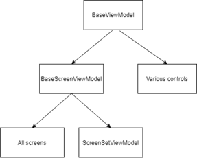
Since CCF started providing a Windows Presentation Foundation (WPF) framework, we have received feedback on WPF features user would like added to the framework. Also, our engineers have continued to improve their WPF expertise, which has led to other improvements. CCF 6.0 includes the requested changes and best practice improvements in the new WPF framework. Some of these changes include:

  • Simplified hierarchy which makes it easier to understand which objects to inherit from.

CCF-6.0-announcement-pic2

  • Centralized style elements to allow users to change the look and feel (skin) of the operator interface to meet their needs.
  • Enhanced controls library that provides common controls for use in creating equipment control.
  • Increased E95 compliance, available with a configurable control panel.
  • Accelerated screen creation is possible with the change in hierarchy organization and the enhanced control library.
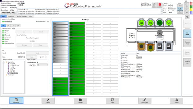
  • Richer set of native WPF screens. In earlier versions, CCF had several native WPF screens, but also had many screens created with WinForms and hosted in WPF. CCF 6.0 has all native WPF screens in the WPF sample operator interface. These screens can be reused, customized, or replaced. (Note: WinForms screens are also still available in CCF 6.0.)

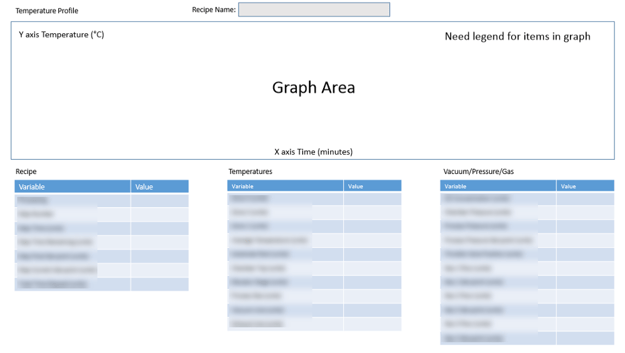
The following image shows the main screen of the WPF operator interface for the CCF atmospheric equipment sample application. Most of the controls on the screen are available for use and customization by CCF developers.

CCF-6.0-announcement-pic3Updated samples

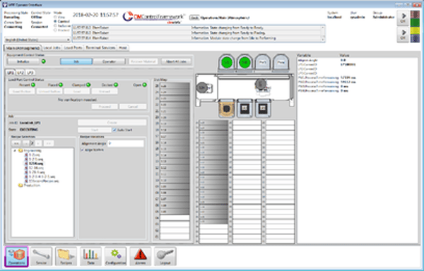
CCF has contained fully functional atmospheric and vacuum sample applications for many years. Over the years, we have improved the functionality for scheduling, simulation, and device interface interaction. However, the samples had always remained the same. With CCF 6.0, the atmospheric and vacuum sample applications were updated to take advantage of the other changes that have been made in CCF. These changes to the samples make them more useful in illustrating the proper use of CCF and providing a better starting point for creating custom applications.

Spring cleaning

CCF was originally released the summer of 2011 making it 10 years-old. Over the years, CCF has had several methods, objects and devices become obsolete. They were not removed from the product for backward compatibility reasons, but they were marked as obsolete. Because CCF 6.0 is a major release, we took the opportunity to do some spring cleaning and remove the obsolete items. CCF is now cleaner and tighter, and using it is much clearer.

Training material and upgrade guide

All the PowerPoint slides, lab documents, and corresponding solutions used for training developers on CCF have been updated for CCF 6.0. We have already successfully used the new training materials with a few customers to help them get started with their equipment control application development.

As part of CCF 6.0, we provide a CCF 5.10 to CCF 6.0 Upgrade Guide that contains detailed instructions on how to migrate applications created using previous versions of CCF to CCF 6.0.

Conclusion

We have been looking forward to the CCF 6.0 release for a long time and are excited for developers to get started using it. We are confident existing users will like the changes and that new users will have a good springboard in getting started with their equipment control application needs. We look forward to working with you and hearing from you.
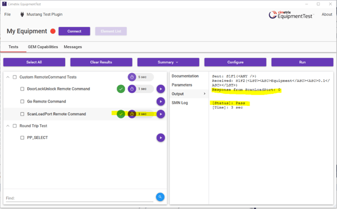
Topics: Industry Highlights, Equipment Control-Software Products, Smart Manufacturing/Industry 4.0, Cimetrix Products

Building a Panel Tool for a Customer using CCF

Posted by Rich Kingsford; Project Manager, CCF Services on Aug 20, 2020 11:38:00 AM

Hi folks! We in the CCF (CIMControlFramework) Services Team love training/consulting on CCF implementations and building custom software for our customers. We’re especially thrilled when we can help our customers ship new equipment and subsequently hear that the equipment successfully ran thousands millions of cycles without issues.

Recently, we enjoyed helping one of our customers build a tool that processes non-wafer substrates. The tool control system included some typical components such as Rorze Hardware Drivers, Light Tower drivers, and a Load Port E84 IO Control, but had some more unique capabilities as well. In this posting we will explore some of the challenges posed and advantages realized from these special capabilities. Before we dive in, please allow me to give a shout out to John Last, our Senior Software Engineer who designed and built most of these capabilities.

Building-panel-tool-1

Process Module Operation Screen

Rather than simply logging data points, our customer wanted a visual representation of temperature over time (minutes). We displayed the categorized variables and their values in tables as well, but the graph updating in real time made it much easier for the operator to visualize the patterns and identify risk events and their sources. The graphing feature needed to be active whether or not the process module operation screen was being displayed. Moreover, It had to handle 3 different step types (Ramp, Dwell and Cool).

Calculating the Y-Axis range for this display presented an additional interesting challenge. The minimum and maximum values were determined by searching all recipe steps and selecting the lowest and highest value setpoints, then subtracting a fixed number from the lowest to get the Y-Axis minimum value and adding a fixed number to the highest value to get the Y-Axis maximum value. The figure below shows how the expected process data should look compared to the observed process data. This allows the operator to see what the equipment is expected to do compared with its actual behavior.

Building-panel-tool-2

Partial FOUP grouping to create a single batch

Our customer required the capability to group multiple partial FOUPs into a single batch. This is especially useful in scenarios where partially filled FOUPs would be used—say, in R&D environments. In other words, we needed to support scenarios where the number of FOUPs needed for processing a batch exceeded the number of load ports. This required us to create Control Jobs with a MtrlOutSpec containing a valid SourceMap with an empty DestinationMap. We relied on SEMI E94’s concept of “Late Announcement of Output FOUP” to specify the input FOUP but not the output FOUP. This allows the scheduler to say, “We know the substrate will go to a different slot, but we won’t tell you which slot until later.”

E90 substrate reading in the Panel solution

As with most tools, each of the substrates has an ID, and this ID must be read and reported to the host. In this case, our host had to verify that the expected ID matched the actual ID. On a successful match, the equipment would then continue the job. If it failed, however, the host would be notified and decide whether to proceed or change something. Capabilities like these maximize throughput and mitigate risks to equipment safety side and production scrap.

Different Panel Types

This machine was required to deal with panels having multiple thicknesses and possible warpage. Therefore we needed to provide a method for an operator, the recipe, and the host to specify the panel type to be processed. None of the variations of panel types were known ahead of time, so we needed methods that handled additional panel types without having to make code changes after the equipment was deployed in production.

The tool also required different substrate mapping parameters for each panel type. Because panel type was specified in the process program referenced in the Process Job, the panel type was not known when the FOUP arrived at the load port. To handle this situation, we customized a standard factory automation SECS II message to communicate the panel type from the host to the tool on arrival of the FOUP.

Conclusion

This equipment was built on an extremely aggressive timeline by a very small team. I was particularly impressed by the team’s ability to grasp the end customer’s requests and creatively explore alternative ways to solve the never-before-seen challenges. In summary: no drama; a few delays; even fewer verbal altercations; just a little frustration; only a little scope creep; and most important, a satisfied factory customer. We all cheered when our customer shipped the tool in 2020.

To find out more about CIMControlFramework and our CCF Services team, or to contact us for a demo, click the button below.

Contact Us

Topics: Industry Highlights, Equipment Control-Software Products, Doing Business with Cimetrix

How we helped a customer deliver a GEM-compliant equipment using CCF

Posted by Rich Kingsford; Project Manager, CCF Services on Jun 4, 2020 2:30:00 PM

Welcome to the first posting in the Cimetrix CIMControlFramework (CCF) Services blog series! While Cimetrix has been providing professional services for many years, in order to better serve the growing demand from many new equipment maker customers worldwide that have purchased our CCF product, Cimetrix earlier this year formed a new CCF Services group, reporting directly to the CEO. Being a senior developer at Cimetrix for the past 15 years in a variety of positions, I was delighted when asked to lead this group. We have an outstanding team of software engineers highly experienced in factory automation, equipment control software and SEMI standards. We are dedicated to ensuring our customers’ success by providing training, consulting, and developing custom solutions for our CCF customers. We love learning about the myriad ways that companies can integrate CCF with their equipment to meet the material handling and factory automation requirements of their factory customers. Our goal for these articles is to share some of the lessons learned and other implementation insights to help you efficiently build manufacturing equipment that is sophisticated, robust, and productive. To this end, our first posting will deal with one of the most common requests we get – enjoy!

- Forward by Brent Forsgren, Director of CCF Services

How we helped a customer deliver a GEM-compliant equipment using CCF

The Goal

One of our recent customers wanted to build a new type of LED manufacturing equipment that could be controlled by a Factory Host using the standard GEM Remote Commands: PP_SELECT (Process Program Select), START, STOP, ABORT, PAUSE and RESUME. The equipment could be delivered in a variety of physical configurations, including 1-to-multiple source cassettes for product material, and 1-to-multiple process modules. It also had multiple destination cassettes to be filled according to the post-process analysis results. The initial instance of the equipment had 4 loadports (LPs) and four process modules (PMs).

The functional requirements were clear – that was the good news. Now for the rest of the story… the project schedule and budget constraints were closing in, so we needed to work quickly and efficiently with the customer to get it done. Sound familiar?

The Approach

The Cimetrix CCF Services team always works closely with the software team of the equipment manufacturer. In this case, we started with one week of mutual discovery and in-depth hands-on training. Team members were fully engaged and picked up the CCF capabilities very quickly. This included even some of the more advanced features, such as developing a scheduler that would control the components of the customer’s application. We regularly fine tune training modules to 1) introduce CCF concepts, 2) expose common challenges and potential approaches, and 3) provide realistic implementation practice exercises. As anticipated, the customer was able to use the results of the training exercises in the actual equipment control solution. We also kicked off the project with our work-breakdown exercise to more deeply explore the unique requirements for their specific equipment type.

After an intense first week, everyone on the project team concluded that CCF would in fact be a strong match for their needs. CCF features direct integration with our CIMConnect, CIM300, and CIMPortal connectivity products to provide full GEM, GEM300 and EDA compliance. Because the Cimetrix connectivity products are deployed in every semiconductor 300mm factory in the world, our customers can be assured that they will meet their customer’s factory automation requirements. In this application, the end customer’s LED factory only required GEM.

To address requirements that may go beyond the basic GEM standards, CCF also provides support for custom remote commands, data publication, and alarm management. Finally, CCF supports integrating custom hardware devices using CCF’s base Equipment Classes.

To prove all was working, we chose the Cimetrix EquipmentTest product to develop and execute a set of unit tests that emulate communications with the factory software using GEM messages. This was not intended to be a comprehensive set, but rather just enough to show the equipment passed round-trip system testing. In this context, round trip means showing that the equipment can move material from the incoming cassette to the aligner to the process module and back into the cassette. EquipmentTest also supports editing message settings and parameters on the fly to experiment with different configurations of a round-trip test.

The Challenge: “The Host is unavailable, but we need to validate that the equipment is both GEM compliant and accomplishes the communication flows the end user requires.”

We get this challenge a lot… Our customers almost always develop the host interface and the embedded control software in parallel and integrate them later in the project. This makes sense at one level, but it does introduce a “chicken and egg” problem for testing this kind of GEM interface. In particular, how can our customer provide evidence that the solution will work with the factory host without testing with the actual host system? Our answer: apply our EquipmentTest custom plugin capability to simulate the end user’s host so we can validate all necessary communication between host and equipment.

Our protocol validation product, EquipmentTest, makes it possible to simulate communications between an equipment control implementation and the host. And although it is impractical to implement scenarios for every possible interaction, we can create enough representative scenarios to be confident the “happy path” (i.e., no errors) will work and that the interface will handle a large handful of “sad path” cases as well.

CCF-Services-Image1

Outcome

We passed all the tests! “Let’s go get some tacos.”

Specifically, we validated that the communications interface supported…

  • Standard GEM Remote Commands
  • Custom Remote Commands
  • Material tracking
  • Data publication

In closing, we must emphasize that our customer should take most of the credit here. Nevertheless, we enjoyed observing, consulting, and testing the equipment. It is always gratifying to see the CCF solution fit so seamlessly into the hardware, execute its commands with optimal timing, and not break anything in the process! Truly a successful, joint team effort.

If the situation above resonates with your current challenges and past experiences, give us a call. We look forward to working with your software engineering team to speed your time-to-market and deliver a high-quality solution quickly, allowing your team members to focus on developing value-added functionality for your customers.

Topics: Industry Highlights, Equipment Control-Software Products, Doing Business with Cimetrix, GEM300