Industry News, Trends and Technology, and Standards Updates

Brian Rubow: Director of Solutions Engineering

Brian Rubow is the Director of Solutions Engineering for Cimetrix. He is well-known within the industry due to his involvement with the SEMI standards committees. He currently serves as the co-chairs for the North America Information and Control Committee, the North America GEM300 Task Force, and the North America DDA Task Force. Rubow has both a bachelor’s and a master’s in Engineering from Brigham Young University.
Find me on:

Recent Posts

Semiconductor Backend Processes: Additional SEMI Standards Related to GEM

Posted by Brian Rubow: Director of Solutions Engineering on Jul 9, 2020 11:30:00 AM

Background

In a few previous blogs I shared how the relatively new SEMI Advanced Backend Factory Integration (ABFI) task force in North America has already decided to promote the adoption of the GEM standard and selective adoption of the GEM300 equipment communication standards. In this blog I will summarize the task force’s plans to consider adoption of additional SEMI information and control standards that are complementary to GEM and GEM300.

Additional SEMI Standards for the Backend Consideration

Many of the standards listed below were developed a few years after GEM300 but are now considered to be part of the modern GEM300 set.

SEMI Designation

Standard Name

E84

Specification for Enhanced Carrier Handoff Parallel I/O Interface

E116

Specification for Equipment Performance Tracking

E116.1

Specification for SECS-II Protocol for Equipment Performance Tracking (EPT)

E142

Specification for Substrate Mapping

E142.1

Specification for XML Schema for Substrate Mapping

E142.2

Specification for SECS-II Protocol for Substrate Mapping

E148

Specification for Time Synchronization and Definition of the TS-Clock Object

E157

Specification for Module Process Tracking

E172

Specification for SECS Equipment Data Dictionary (SEDD)

E173

Specification for XML SECS-II Message Notation (SMN)


E84 Carrier Handoff

E84 Carrier Handoff is the only standard in this list that not a GEM standard because it deals with a separate parallel I/O interface. This interface is completely independent of GEM, although it is coordinated with E87 Carrier Management when both are supported. However, since E84 Carrier Handoff is often included in the GEM300 discussions and requirements, it is worth discussing here because it is a standard that the Backend industry should selectively adopt.

GEM-Backend-2-1

The E84 standard defines the handshake signals for use in a parallel I/O (PIO) interface to automate carrier delivery and carrier removal. The automated material handling system (AMHS) might use either an automated guided vehicle (AGV) or overhead transport (OHT) system, yet either way, the material is delivered in a carrier. E84 is widely used and accepted in every semiconductor wafer fab (front end) and an obvious choice for backend manufacturing when delivering carriers.

E116 Specification for Equipment Performance Tracking

E116 Equipment Performance Tracking was discussed in an earlier blog since there are plans to update this specification to better support backend operations. E116 is applicable to any manufacturing equipment in any industry because it is largely based on SEMI E10 principles which define generic terms for measuring any equipment’s reliability, availability and maintainability. As a bonus, each major component in the equipment can also be modelled to track its productivity.

E142 Specification for Substrate Mapping

E142 Substrate Mapping and its subordinate standards (E142.1 XML Schema for Substrate Mapping and E142.2 SECS-II Protocol for Substrate Mapping) define generic substrate maps and how to transfer them to and from an equipment through a GEM interface. Substrate maps are two dimensional arrays of data that correspond to a physical substrate—which may be a wafer, strip or tray. The map defines the dimensions of the substrate, significant locations on the substrate, and can include data about the locations (such as a numbering scheme for unambiguously identifying specific locations). For example, E142 can be used to tag “known good” devices on a substrate.

Some equipment types require a substrate map before processing can proceed. Some equipment can generate substrate maps. And some equipment both require a substrate map before processing and generate an updated substrate map after processing is completed. In E142, the substrate map is expressed in an XML file that conforms with the E142 XML schema. A lot of backend equipment need substrate maps for normal operation, so E142 is an obvious choice. Note that E142 is currently undergoing some interesting improvements via the ABFI task force to store additional data needed to address enhanced traceability requirements.

Substrate mapping is an excellent demonstration of horizontal communication implemented using GEM. Horizontal communication is when data is shared directly from one equipment to another equipment. Traditionally, horizontal communication in GEM is implemented indirectly; one equipment passes data to the host and then the host passes that data on to the equipment that needs it. In this sense, the GEM host acts as a type of broker between units of equipment.

There are significant advantages in using this indirect style of horizontal communication. For example, Equipment A might inspect a substrate, generate a substrate map and send it to the host. Equipment B might later request the substrate map from the host.

GEM-backend-2-2The benefit of using a GEM host between the equipment to realize this use case is that both Equipment A and Equipment B are only required to implement GEM—which they should be doing anyway. The equipment are not required to support additional protocols and/or custom message sequences, or to be tested against specific equipment interfaces. If each equipment follows the GEM standard, they can all be integrated into the factory system and share data through the GEM host.

E148 Specification for Time Synchronization and Definition of the TS-Clock Object

A lot of data collected in the factory is only useful when properly timestamped. Moreover, timestamps can only be compared among data from multiple sources when those timestamps are synchronized. This is where SEMI E148 enters the picture.

The E148 Time Synchronization specification requires equipment to support the industry standard Network Time Protocol (NTP) and share information about its implementation. And NTP software synchronizes computer clocks.

Because the backend industry segment is trending towards more and more data collection, it is critical to have proper timestamping for that data, and therefore time synchronization for its sources. A full E148 implementation may not be required, but certainly the equipment should support NTP as described in E148. If an equipment control systems is composed of multiple computers, E148 states that they should all be synchronized with a single computer designated as the master, which is a good idea if the other computers are generating data with timestamps.

E157 Specification for Module Process Tracking

E157 Module Process Tracking does not apply to all backend equipment. To use E157 Module Process Tracking, there must be at least one process module (aka a process chamber) which processes one substrate or a batch of material at a time. If multiple substrates are processed at a time but each having different start and stop times, then this specification cannot be applied.

E157 Module Process Tracking defines a very simple processing state model which is implemented independently for each process chamber.

GEM-backend-2-3The state model reports when the process chamber is either idle (Not Executing) or processing a recipe (Executing). And when processing a recipe, each time an individual step in the recipe starts, completes, or fails, this is reported. It is up to the implementer to decide what constitutes a recipe step. In my experience, most equipment that could adopt E157 have already implemented something very similar using a set of GEM events. However, rather than implementing something custom, it is better for end users and equipment manufacturers alike if the implementations are standardized.

E157 is a prime example of an exceptionally simple and well-written standard built on top of GEM technology that is easy to implement and provides a lot of end user value. Hopefully the ABFI task force can develop something based on E157 principles that is well suited for backend equipment that cannot accommodate the full scope of the current standard.

E172 Specification for SECS Equipment Data Dictionary (SEDD)

Go back in time (not that far, actually), and “GEM documentation” meant a stack of printed documentation on paper that was expected to be delivered with the equipment. Today “GEM documentation” means an MS Word document, PDF file, Excel spreadsheet, or some other electronic representation of the same information. Nearly any digital format is acceptable.

Nevertheless, E172 SECS Equipment Data Dictionary is the future of GEM documentation. The GEM documentation is provided in a standardized electronic XML format called an SEDD file. E172 defines a standard XML schema. The initial version of this schema included only basic information about a GEM interface. This was expanded in a later version to include several more details. Soon, I hope to report that the E30 GEM standard has been modified to officially include SEDD files as one form of documentation. Additionally, this should include enhancing the GEM standard to allow an SEDD file to be transferred directly through the GEM interface. This will significantly improve GEM’s plug-and-play capability by enabling factory host software to consume an SEDD file and automatically configure the GEM host software to support an equipment’s specific implementation of GEM and GEM messages.

As the backend industry segment is increasingly implementing GEM in its factories, I expect SEDD files to be required from all backend equipment manufacturers.

E173 Specification for XML SECS-II Message Notation (SMN)

In order to diagnose problems in a GEM interface, it is essential to have logging for the GEM messages transferred between the host and equipment. Typically, both the GEM host and equipment’s GEM interface will provide logging functionality. In the past, a notation called SML (SECS Message Language) was used for logging GEM messages. Unfortunately, SML was never standardized or even sufficiently well defined. As result, there are many different variations of SML throughout the world. While SML notation itself is relatively easy to generate with software, the breadth of implementation variations makes it difficult to automatically parse and use.

Fortunately, the SEMI North America GEM300 task force created E173 XML SECS-II Message Notation (SMN) to solve this problem. SMN defines an XML schema that anyone can use to document and log GEM SECS-II messages. The schema is feature rich allowing for both minimum and elaborate XML decoration. As an example of its usefulness and flexibility, the E172 SEDD schema references the SMN schema file. Because SMN is based on XML, it is both very easy for software to generate and consume. There are numerous software tools and libraries available in virtually every software programming language for working with XML. Using SMN with GEM allows GEM to continue to send and receive messages in an efficient binary format, yet still enjoy the benefits of using a decorated, human-readable text notation for diagnosing issues.

I expect the ABFI task force to recommend that the backend industry segment adopt SMN in all equipment GEM interfaces.

Conclusion

As backend factories adopt GEM, we expect that they will also want to use the latest technologies with it, including SMN, SEDD, Module Process Tracking and Equipment Performance Tracking. Watch for more details and updates from the SEMI Advanced Backend Factory Integration task force as its work progresses—and feel free to join this initiative if you want to help steer and accelerate this activity!

To download the GEM300 White Paper, click the button below.

GEM300


Topics: Industry Highlights, SECS/GEM, Doing Business with Cimetrix, GEM300

Semiconductor Back End Processes: Selective GEM300 Adoption

Posted by Brian Rubow: Director of Solutions Engineering on Jun 24, 2020 11:15:00 AM

GEM and GEM300 Adoption

In a previous blog I shared how the relatively new SEMI task force in North America called “Advanced Back End Factory Integration” (ABFI) has already decided to promote the adoption of the GEM standard. In this blog I will explain how the task force is also planning to selectively adopt what is often called the GEM300 set of standards. I say “planning” because this is a work in progress and subject to the standardization process in which we strive for consensus among the participants. However, one can argue that this plan should not be particularly controversial since the GEM300 standards have already been adopted by several major manufacturers of semiconductor back end equipment.

What are the GEM300 Standards?

There is no official “GEM300” definition, but at a minimum, all the experts agree that the GEM300 set of SEMI standards includes the following:

SEMI Designation

Standard Name

E5

Specification for SEMI Equipment Communications Standard 2 Message Content (SECS-II)

E30

Specification for the Generic Model for Communications and Control of Manufacturing Equipment (GEM)

E37

Specification for High-Speed SECS Message Services (HSMS) Generic Services

E37.1

Specification for High-Speed SECS Message Services Single Selected-Session Mode (HSMS-SS)

E39

Object Services Standard: Concepts, Behavior, and Services

E39.1

SECS-II Protocol for Object Services Standard (OSS)

E40

Standard for Processing Management

E40.1

Specification for SECS-II Support for Processing Management

E87

Specification for Carrier Management (CMS)

E87.1

Specification for SECS-II Protocol for Carrier Management (CMS)

E90

Specification for Substrate Tracking

E90.1

Specification for SECS-II Protocol for Substrate Tracking

E94

Specification for Control Job Management

E94.1

Specification for SECS-II Protocol for Control Job Management (CJM)


Seen together like this in a table, it seems like a lot to study and learn. And it is daunting. However, it is important to remember that most of the primary standards (like E87 and E90) also have a subordinate standard (like E87.1 and E90.1) that defines how to implement the standard using SECS-II. Although this nearly doubles the length of the list, these “.1” standards are really just extensions of the primary standard, and are all relatively short specifications. Each of these core GEM300 standards defines specifically how to use and augment the GEM standard to implement specific factory automation requirements and production operational scenarios. Basically, they work together like this:

GEM-for-Backend-2.1

SEMI E37 (High-Speed SECS Messaging Services), E5 (SECS-II) and E30 (GEM) are the core standards for any modern GEM implementation—regardless of the GEM300 additions—so of course they apply. Each of the additional GEM300 standards builds on top of E30 and E5 to define general features for data collection, alarm handling, collection event reporting and the messaging library. For example, E87 (Carrier Management) deals with the load port services, carrier delivery, and carrier removal. E90 (Substrate Tracking) reports all substrate movement from the carrier to the process chamber and any intermediate movement. E40 (Processing Management) and E94 (Control Job Management) determine which substrates to process, which recipes to use and the substrate destinations. Finally, E39 (Object Services) defines general object handling for all of the standards.

Even though the diagram shows silicon wafers—since semiconductor front end factories use this set of GEM300 standards nearly universally—their applicability goes well beyond 300mm silicon wafer processing. However, if an equipment does not deal with the substrates (material) or substrate delivery directly, then it is best just implementing GEM rather than GEM300.

How can these SEMI standards be applied to other equipment?

E87 Carrier Management

Certainly, any equipment dealing with a FOUP (front-opening universal pod) that holds silicon wafers can adopt E87 Carrier Management to manage the load ports and carrier validation. But E87 Carrier Management is written in a manner flexible enough that equipment handling many other types of material can adopt it. Here are the criteria:

    1. The material arrives in a container of some sort.

      The shape of the container, the number of slots in the container and the orientation of the slots do not matter. The container can be a rectangular tray with pockets. It can also be round with pockets. E87 Carrier Management refers to these containers as carriers.
    2. The material slots in the container can be ordered.

      In a FOUP, the material is in a horizontally stacked orientation. However, the principles of E87 Carrier Management can also apply to other material orientations. Whatever the container type, there needs to be clearly defined slot numbering. E87 Carrier Management only defines the order for a stacked container; therefore, other container styles need standardization.

With these two criteria, E87 Carrier Management can be applied to add value to the equipment by supporting an increased level of factory automation.

What features determine whether E87 Carrier Management can be adopted?

    1. Carrier (Container) ID

      If there is a carrier ID of some sort, it is of course very useful for implementing carrier ID verification. The carrier ID can be a barcode or any other type of identifier. But even if there is no carrier ID (even a barcode would suffice), then while under remote control the host can assign an ID to the carrier. Alternatively, while under local control the equipment software can generate a unique carrier ID.

    2. Carrier (Container) ID Reader

      E87 Carrier Management anticipated that a unit of equipment might not have a carrier ID reader. It also anticipated that a carrier ID reader might be out of service or defective, and therefore should be ignored. Not having a carrier ID reader means that you will not have the benefit of verifying that the correct container has arrived.

    3. Number of Slots in the Container

      A standard FOUP for silicon wafers has 25 slots. But the number of slots in a container is not limited or restricted.

When can’t E87 Carrier Management be applied?

For E87 Carrier Management to be applied, the material needs to arrive and/or depart in some sort of container. If material arrives and departs continuously without any container, such as on a conveyor, then there is no container or load port for E87 Carrier Management to manage. Of course, GEM can still be applied without E87 and the other GEM300 standards, although E90 Substrate Tracking might still be useful.

What are the benefits of using E87 Carrier Management?

E87 Carrier Management provides quite a few benefits to any equipment that can adopt it.

  • Confirmation that the correct container arrived at the equipment
  • Confirmation that the container has the expected material in its various locations
  • Reporting current load port states (e.g., occupied, ready for unloading, ready for loading)
  • Placing a load port in and out of service, such as for maintenance and repair
  • Notifying the equipment when a container will be arriving
  • Managing container storage
  • Reporting when the material from a container is nearly completed processing
  • Load port identification
  • Assigning substrate IDs

E90 Substrate Tracking

The “substrate” term is not restricted to silicon wafers, but rather applies to any type of product material. This generalization of the substrate term means that E90 Substrate Tracking can be applied to many different types of equipment.

Normally substrate tracking is considered in terms of fixed substrate locations, such as a slot in a container, a specific location in a pre-aligner, the end effector of a robot arm, or a specific process chamber. However, just a like a robot for handling silicon wafers can have multiple arms for handling multiple substrates, a conveyor can be similarly modeled to have multiple substrate locations. For example, if a conveyor can hold 50 small substrates at a time, then it could be modeled with 50 substrate locations for high-precision material tracking. Doing so allows E90 to be used to track substrates even while on a conveyor. The time each substrate is placed on a conveyor can be used to deduce the order of the material on the conveyor.

E90 Substrate Tracking also provides for substrate ID verification. This is only possible when the substrates have an identification code that can be read, such as a barcode or 2D data matrix, and when the equipment has the hardware capable of reading the identification code. When both are present, substrate ID verification can allow the factory to confirm each substrate before processing, and thereby reduce scrap.

When an equipment transports and processes multiple units of material internally using any type of container, it is called batch processing. E90 Substrate Tracking also supports this method by identifying batch locations and by providing data collection features specific to batch movement.

When can’t E90 Substrate Tracking be applied?

In order to use E90 Substrate Tracking, the equipment must have at least two substrate locations and work with some type of substrate. Without these there is no benefit in implementing E90 Substrate Tracking.

What are the benefits of using E90 Substrate Tracking?

E90 Substrate Tracking provides many benefits to any equipment that handles material.
  • Providing history of substrate movement, including timestamps for each location change
  • Substrate identification
  • Substrate location identification
  • Factory substrate verification, including the automated rejection of invalid substrates
  • Providing processing status for each substrate
  • Implementing virtual substrate tracking for lost substrates

E40 Processing Management

E40 Processing Management creates a list of materials to process and the name of the recipe to use. When using silicon wafer substrates, this list is either in the form of a carrier ID and a set of slot numbers, or a list of substrate IDs.

When can’t E40 Processing Management be applied?

If an equipment processes material continuously without having a discrete set of material that is known and identified ahead of time, you cannot apply E40 Processing Management. E40 Processing Management assumes that you have a specific set of material to process. If each substrate is simply processed as it arrives, then you are better off just using GEM’s PP-SELECT remote command to choose the correct recipe.

What are the benefits of using E40 Processing Management?

E40 Processing Management provides multiple benefits when it can be applied to an equipment:

  • Easily configure the equipment to process a specific set of material with a specific recipe. For example, 20 substrates can all be processed with the same recipe, or each with a different recipe.
  • Allows the equipment to support process tuning in which specific default settings in a selected recipe can be overwritten with new values. This is far easier than creating a proliferation of nearly identical recipes.

E94 Control Job Management

E40 Processing Management can be used in a standalone fashion but is usually implemented in conjunction with E94 Control Job Management. I recommend implementing both. Even if you don’t need all the extra features of Control Job Management, it adds very little overhead and is easy to use.

When can’t E94 Control Job Management be applied?

E94 Control Job Management cannot be used without E40 Processing Management, because its primary function is to manage the E40 process jobs. Therefore, its applicability is subject to the same criteria as E40 Processing Management.

What are the benefits of using E94 Control Job Management?

E94 Control Job Management has some features that benefit some equipment:

  • Allows material to arrive in one container and depart in another. This is beneficial when the source container needs to be kept uncontaminated by the effects of a process.
  • Allows material to be sorted based on some criteria. This is beneficial when sorting takes place based on inspection and/or other conditions, and the material is subsequently routed to different destination containers based on the sorting.
  • Manages a set of process jobs. For example, one can abort, pause or resume all process jobs.

How does all of this apply to the back end industry segment?

Factories must decide if they want the benefits of GEM300. Although E90 Substrate Tracking can be applied to most equipment, E87 Carrier Management, E40 Processing Management and E94 Control Job Management are only applicable to the equipment that deliver and/or remove material in containers. The features of each standard may not seem remarkable in and of themselves, but it is important to remember that these features have been implemented in a standardized way that many equipment manufacturers and their factory customers around the world have all agreed to follow—and that is truly remarkable.

One of the primary benefits of the GEM300 standards is the factory’s ability to move material to the equipment and process it in any order. The term “process” is used very loosely with the understanding that in addition to material transformation, inspection, metrology, sorting, testing, packaging, and other manufacturing activities are all types of processing. The material can be moved from any equipment to any equipment. This flexibility is a key to the success of modern integrated circuit manufacturing. It allows for the fabrication of many products without moving equipment or setting up conveyors. It allows process steps to be added or removed at any time. It enables the optimum use of inspection and metrology equipment since the same equipment can be used before and after any process step. The GEM300 standards directly support this flexibility.

The SEMI Advanced Back End Factory Integration task force plans to standardize the criteria for determining which standards apply based on an equipment’s functionality. What I’ve explained in this posting is just the starting point for this work—there is much more to be done. We welcome more participants on the task force to ensure the standardization is done accurately and efficiently.

Contact Us

Topics: Industry Highlights, SECS/GEM, Doing Business with Cimetrix, GEM300

Semiconductor Back End Processes: Adopting GEM Judiciously

Posted by Brian Rubow: Director of Solutions Engineering on May 14, 2020 10:20:17 AM

Equipment Communication Leadership in Wafer Fabrication

For many years the semiconductor industry’s wafer fabrication facilities, where semiconductor devices are manufactured on [principally] silicon substrates, have universally embraced and mandated the GEM standard on nearly 100% of the production equipment. This includes the complete spectrum of front end of line (FEOL – device formation) and back end of line (BEOL – device interconnect) processes and supporting equipment. Most equipment also implement an additional set of SEMI standards, often called the “GEM 300” communication standards because their creation and adoption coincided with the first 300mm wafer manufacturing. Interestingly, there are no features in these standards specific to a particular wafer size.shutterstock_405869995_backend

Together, the GEM and GEM 300 standards have enabled the industry to process substrates in fully automated factories like Micron demonstrates in this video and GLOBALFOUNDRIES demonstrates in this video.

Specifically, the GEM 300 standards are used to manage the following crucial steps in the overall fabrication process:

  • automated carrier delivery and removal at the equipment
  • load port tracking and configuration
  • carrier ID and carrier content (slot map) verification
  • job execution where a recipe is assigned to specific material
  • remote control to start jobs and respond to crisis situations (e.g., pause, stop or abort processing)
  • material destination assignment after processing
  • precise material location tracking and status monitoring within the equipment
  • processing steps status reporting
  • overall equipment effectiveness (OEE) monitoring

Additionally, the GEM standard enables

  • the collection of unique equipment data to feed numerous data analysis applications such as statistical process control
  • equipment-specific remote control
  • alarm reporting for fault detection
  • interaction with an equipment operator/technician via on-screen text
  • preservation of valuable data during a communication failure

Semiconductor Back End Process Industry Follows the Lead

After wafer processing is completed, the wafers are shipped to a semiconductor back end manufacturing facility for packaging, assembly, and test. Historically this industry segment has used GEM and GEM 300 sporadically but not universally. This is now changing.

In North America, SEMI created a new task force called “Advanced Back end Factory Integration” (ABFI) to organize and facilitate this industry segment’s implementation of more robust automation capabilities. To this end, the task force is charged with defining GEM and GEM 300 support in back end equipment, including processes such as bumping, wafer test, singulation, die attach, wire bonding, packaging, marking, final test and final assembly. As its first priority, the task force has focused on updating the SEMI E142 standard (Substrate Mapping) to enhance wafer maps to report additional data necessary for single device traceability. Soon the task force will shift its focus to define GEM and GEM 300 back end use cases and adoption more clearly.

Why GEM?

GEM was selected for several reasons.

  • A lot of the equipment in the industry already have GEM interfaces.
  • GEM provides two primary forms of data collection that are suitable for all data collection applications. This includes the polling of equipment and process status information using trace reports where the factory can collect selected variables at any frequency. Additionally, collection event reports allow a factory system to subscribe to notifications of just the collection events it is interested in, and to specify what data to report with each those collection events.
  • Most of the equipment suppliers have GEM experience either from implementing GEM on the back end equipment or from implementing GEM on their frontend equipment.
  • Factories can transfer experienced engineers from semiconductor frontend facilities into the back end with the specific goal of increasing back end automation.
  • GEM has proven its flexibility to support any type of manufacturing equipment. GEM can be implemented on any and all equipment types to support remote monitoring and control.
  • GEM is a highly efficient protocol, publishing only the data that is subscribed to in a binary format that minimizes computing and network resources.
  • GEM is self-describing. It takes very little time to connect to an equipment’s GEM interface and collect useful data.
  • GEM can be used to control the equipment, even when there are special features that must be supported. For example, it is straightforward to provide custom GEM remote commands to allow the factory to determine when periodic calibrations and cleaning should be performed to keep equipment running optimally.

Improved Overall Equipment Effectiveness Tracking

The ABFI task force has already proposed some changes to the SEMI E116 standard (Specification for Equipment Performance Tracking, or EPT). EPT is one of several standards that can be implemented on a GEM interface to provide additional standardized performance monitoring behavior beyond the GEM message set. This standard already enables reporting when equipment and modules within the equipment are IDLE, BUSY and BLOCKED. A module might be a load port, robot, conveyor or process chamber. When BUSY, this standard requires reporting what the equipment or module is doing. When BLOCKED, this standard requires reporting why the equipment or module is BLOCKED.

After analyzing the requirements of the back end industry segment, the task force decided to adopt and enhance the EPT standard. For example, the current EPT standard does not make any distinction between scheduled and unscheduled downtime. However, a few minor changes to E116 would allow the factory to notify the equipment when downtime is scheduled by the factory, greatly enhancing the factory’s ability to track overall equipment effectiveness and respond accordingly.  

Additional Future Work

Many of the GEM 300 standards can be applied to some of the back end equipment when applicable and beneficial. The task force is defining specific functional requirements and evaluation criteria to make these determinations and publish the resulting recommendations in a new standard. Representatives from several advanced back end factories are already closely involved in this work, but more participation is always welcome. For more information, click the button below!

Contact Us

Topics: Industry Highlights, SECS/GEM, Semiconductor Industry, Customer Support, Doing Business with Cimetrix, Cimetrix Products

Cached Data: A New Feature in EDA Freeze 3

Posted by Brian Rubow: Director of Solutions Engineering on Jan 22, 2020 11:15:00 AM

Background

Several years ago, I was working with a client implementing EDA who wanted to collect data at higher than typical rates using the EDA trace data collection feature (essentially periodic data polling). The typical EDA data collection rate I was used to was 10 Hz, with a couple of clients implementing 20 Hz or even 40 Hz. This client, however, wanted to collect data at about 1000 Hz. This was a lot faster than we normally could accomplish, especially since the software timers and clock functionality in Windows are really designed for about 15 ms intervals. Therefore, the normal means of implementing the data collection was not going to work very well.

With a little creative thinking, I came up with a solution. Instead of using trace data collection, I decided to try event data collection. Every 1 second, I triggered an event notification and provided 1000 data samples with the event that had been collected at 1 ms intervals and stored. The 1000 samples were presented to the EDA client as an array of data, which EDA supports directly, and this solution worked very well. I also found that this approach used surprisingly few resources to implement and transmit, largely because the data is so compact. It was also very reliable.

Although this event with array data solution worked in this very specific situation, there were a few drawbacks. First of all, the client could not choose the data collection interval. Normally with trace data collection the client chooses the data collection rate to meet the needs of a specific data collection application. Secondly, the client receiving the data had to know what the data meant. The client application software had to be programmed to understand that each value in the 1000 sample array represented data collected every 1 ms. Finally, I could not use the trace start trigger and stop trigger to automatically enable and disable the reporting of the data collected. Normally, trace data collection can be started and stopped automatically to collect data between specific equipment events, which is a nice feature to focus data collection between specific processing steps or other meaningful activities.

EDA Freeze 3

A couple of years ago, the SEMI North America DDA (Diagnostics and Data Acquisition) task force, which I co-lead, decided to begin work on the next version of the EDA standards suite, commonly referred to as EDA Freeze 3. As part of this work, I raised an issue that I wanted our task force to address. That is, I wanted to be able to collect data using the EDA standard at higher frequencies than the typical 10 Hz available using today’s trace data collection. In particular, I wanted to leverage what I had learned using the event data array solution to report data collection at 1000 Hz and faster, and make this an integral part of the EDA standard without the limitations of my current solution. This new feature is now called Cached Data.

Cached Data Features

The basic principle behind this new feature is simple. First, allow the EDA client to define a Cached Data Request and specify the reporting frequency, data collection frequency, and other attributes like the number of samples, a start trigger, a stop trigger, and whether or not the triggers are cyclical. Then have the EDA server report the data for each parameter as a compact data array.

For example, an EDA client might ask for a parameter at a collection interval of 0.1 ms (10 KHz) and a reporting interval of 1 second. The result would be a set of Cached Data Reports that look like this:

EDA-Freeze-3-1-1

The equipment would collect the data every 0.1 ms and store the values for 1 second, and then send the Cached Data Report with the collected values in a tightly packed array. The EDA client would receive the data once per second and would know the data collection frequency.

Limitations

There are some limitations to the Cached Data proposal. For example, this type of data array reporting is only practical for some data types like integers, floats, Booleans and bytes. This type of data reporting is not practical for structured data or strings. Moreover, not all data can or should be collected at such high rates. Collecting data at these high rates requires robust software specifically designed for high-speed data collection. Therefore, the EDA proposal includes a way for parameter metadata to specify where the cached data feature can be used, and includes the specific minimum and maximum data collection frequencies. Therefore, the Cached Data feature is expected to be used for a limited subset of the available parameters for which the EDA server is specifically designed to provide such high-speed data collection.

gRPC & Protocol Buffers

The proposed EDA Freeze 3 standards also include the use of gRPC and Protocol Buffer technology, thereby moving EDA away from SOAP/XML over HTTP. gRPC with Protocol Buffers is a solution for a binary interface. Prelimiary test results reported to the DDA task force show dramatic throughput improvements and reduced bandwidth requirements for EDA. Additionally, the testing confirmed that reporting data in compact arrays is far more efficient for transmitting large amounts of data. In other words, the Cached Data feature is expected be even more effective due to this EDA protocol change.

SEMI Voting

Soon a new voting cycle for SEMI standards will begin where we vote on new versions of the standard. The Cached Data feature is included in two SEMI ballots: ballot 6553, a major revision of the SEMI E134 SPECIFICATION FOR DATA COLLECTION MANAGEMENT, and ballot 6527, a major revision of the SEMI E125 SPECIFICATION FOR EQUIPMENT SELF DESCRIPTION. Both are planned for voting in SEMI voting cycle 2 in 2020. Task force members are currently reviewing the latest revision of the proposed ballots.
Studies have already shown vast improvements in factory applications when collecting data at 10 Hz instead of 1 Hz. The increased performance of EDA Freeze 3 will allow the industry to dramatically improve manufacturing processes even more when data can be collected and reported at rates of 1000 Hz, 10 KHz, and beyond.

Topics: Industry Highlights, Semiconductor Industry, EDA/Interface A, EDA Best Practices

Why implement a SECS GEM driver?

Posted by Brian Rubow: Director of Solutions Engineering on Dec 12, 2019 2:15:00 PM

A SECS GEM driver can be looked at from a factory or equipment supplier perspective. I will discuss both of them in that order.

Factory Perspective

A little background:

semiconductor-factory-1

From a factory perspective, a SECS GEM driver is the host software that talks to an equipment’s GEM interface. It allows the factory to take advantage of the features implemented in each equipment’s GEM interface. However, what the factory can do with an equipment’s GEM interface is also limited by what the equipment supplier has included in that interface. The GEM standard is very flexible and scalable, which accounts for the widespread and growing adoption of GEM technology—it can be adapted to any manufacturing equipment and market segment.

It is possible to implement features in a GEM interface. But this also means that just having a GEM interface on the equipment does not ensure that it has been correctly designed to meet the factory’s expectations. An equipment supplier’s poor implementation of GEM can frustrate a factory’s plans for Smart Manufacturing by not providing features that the factory expects that could have been implemented. The tendency of most equipment suppliers is to implement the absolute minimum functionality in a GEM interface to save money. Therefore, it is the responsibility of the factory during equipment acceptance to evaluate the GEM interface to make sure that it is robust and has the full set of required features. The factory must have a clear vision of its needs both initially and later as its Smart Manufacturing goals are realized. It is not unusual for a factory to request an upgrade to an equipment’s GEM interface with more features, but these modifications usually come at a cost.

Although a factory’s SECS GEM driver must be adaptable to different suppliers’ GEM implementations, it only needs to support the specific features that the factory uses. For example, if the factory is only concerned about alarm and event report notification, then it does not need to support the messages for recipe management, remote control or trace data collection. As such, the investment in a SECS GEM driver is proportional to the number of GRM features that are utilized. However, the SECS GEM driver should also support variations in alarm and collection event implementations, because each equipment type will support a unique set of alarms and a unique set of collection events with unique data variable for event reports. Moreover, from equipment type to equipment type, the same collection ID might have different meanings. The SECS GEM driver therefore needs an ability to adapt by having a method to characterize the GEM implementation (such as a list of available collection events) and the ability to map a general capability to the actual implementation (such as “material arrived” = collection event ID 5).

So why would a factory want to use SECS GEM technology?

factory-alan-1In order to reach the goals of Industry 4.0 and Smart Manufacturing, factories must be able to monitor and control manufacturing equipment remotely. Therefore the equipment must have a software interface to provide this functionality and the factory must be able to access and use this interface.

Factories could let the equipment suppliers choose their own implementation technologies for this kind of capability, but as a result, different suppliers might take a different approach for every equipment type. This would be tremendously expensive and resource intensive. It is far better to standardize on one or two technologies, and ideally, one that is proven to work and known to have all of the necessary features. This allows the factory to achieve its goals with minimum investment, focusing instead on using the equipment interface in creative ways to improve manufacturing.

SECS GEM is the most proven technology already widely used across the globe and supported by the most sophisticated and automated industry in the world; semiconductor manufacturing. It is also widely adopted several other industries, making it a safe choice. The range of production applications supported by SECS GEM data collection include productivity monitoring, statistical and feedback/feedforward process control, recipe selection and execution tracking, fault detection and classification, predictive maintenance, reliability tracking, and many more. By contrast, alternatives to SECS GEM have so far been demonstrated to be incomplete or immature solutions. 

What specifically can you do with the SECS GEM technology?

  1. Collection Events: Be notified when things happen at the equipment, such as when processing or inspection begins and completes, or when a particular step in a recipe is reached.
  2. Collection Event Reports: Collect data with collection events. The host chooses what data it wants to receive. For example, track the ID of material arriving and departing from the equipment, or components placed on a board.
  3. Alarms: Be notified when bad or dangerous things are detected, receive a text description of the alarm condition, and when the issue is cleared.
  4. Trace Data Collection: Tell the equipment to report status information (software and/or hardware data) at a specific interval. For example, track digital and/or analog sensors during processing at 10 Hz frequency.
  5. Recipes: Upload, download, delete and select recipes as desired, whether in ASCII or binary formats. Make sure that the right recipe is run at the right time to eliminate misprocessing and minimize scrap. Track when someone changes a recipe.
  6. Remote Commands: Control the equipment, such as when to start, stop, pause, resume and abort. Custom commands, such as calibrate, skip or anything else can be supported.
  7. Equipment Constants: Configure and track the equipment configuration settings remotely.
  8. Terminal Services: Interact with the equipment operator remotely or provide instructions for the operator.
  9. Extensions: There are numerous extensions to GEM that can be supported but are not yet form requirements. For example, implement wafer or strip maps from E142 to provide and report details about material in XML format.

Equipment Supplier Perspective
AdobeStock_12291008-1

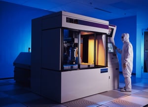
From an equipment supplier’s perspective, a SECS GEM driver is the software used to implement GEM technology on the equipment. In other words, the software to create a GEM interface. The equipment-side software requirements are inherently more complex that the host SECS GEM driver. This is because the equipment-side features are precisely defined by the GEM standard and should be implemented to the fullest extent possible. By contrast, the host can really do whatever it wants, so a limited implementation may be sufficient. In an ideal situation, the equipment supplier will implement just enough features in its GEM interface to satisfy all of its customers and therefore ship an identical GEM interface to all its customers. It is up to the equipment supplier to decide what GEM features to implement and how to adapt them for a particular type of equipment, but the factory should provide clear expectations about its planned use of the interface. It is also the factory’s responsibility to qualify the GEM interface during equipment acceptance. Note that it is not uncommon for factories to withhold partial equipment payment until the GEM interface has also passed its own acceptance.

Some equipment suppliers include the GEM driver as a standard feature on all equipment. This is ideal because it makes the GEM interface much easier to support and distribute. Some equipment suppliers only install GEM when it is specifically purchased. This often results in installation problems because the field technicians may or may not be knowledgeable enough or specifically trained to do this correctly. Other equipment suppliers include the GEM driver on all equipment, but only enable it when the feature has been purchased. This is better than attempting GEM interface installation after equipment delivery because the GEM interface can often be enabled with a simple equipment configuration setting.

Here are some key reasons for implementing a SECS GEM driver:

1. “One ring to rule them all”

By implementing a GEM interface, an equipment supplier can avoid having to implement multiple interfaces. Because GEM is the most feature complete option, the it should be implemented first and Thoroughly integrated with the equipment control and user interface software. If other protocols must be supported, they can usually be mapped onto the GEM capabilities or a separate external system because they only include a subset of GEM functionality.

2. Equipment Supplier Application Software

If the GEM implementation includes support for multiple host connections, then the GEM interface can be used by the equipment supplier itself for many applications. For example, an equipment supplier can develop a software package that monitors and controls their specific equipment at a factory. This can run simultaneously and independently while the factory GEM host software is connected. Many factories are willing to buy applications from the equipment supplier that enhance the productivity of the equipment they have purchased. As an example, equipment suppliers are better equipped to develop predictive maintenance applications that determine when parts are approaching failure and need replacement. These applications can save the factory time and money by avoiding unscheduled downtime. Other applications can also be developed by equipment suppliers to analyze and optimize equipment execution.

3. Competitive Advantage

A well implemented GEM interface can differentiate a supplier’s equipment from that of its competitors. Factories are beginning to recognize the value in controlling and monitoring equipment remotely, and know that a poor GEM interface contributes nothing to a factory’s Smart Manufacturing initiatives. A GEM interface that goes the extra mile to be truly useful empowers the factory to excel at Smart Manufacturing and to be far more productive. Selling equipment in today’s market without a GEM interface is like selling a television without a remote. On the other hand, providing a fully featured GEM interface is like selling a smart television.

Final Words

Experts on GEM technology are available all over world. Because GEM is a mature industry standard and well defined, it can be implemented by anyone in a range of different programming languages and operating systems. however, to save time I recommend using a commercially available product rather than developing the complete GEM interface from scratch. This can save massive amounts of time and effort, and ensures the quality of the resulting implementation.

To speak with a Cimetrix GEM expert, or to find out more about our GEM software products, you can schedule a meeting by clicking the link below.

Ask an Expert

Topics: Industry Highlights, SECS/GEM, Semiconductor Industry, Smart Manufacturing/Industry 4.0

Industry Standards Activity Report November 2019

Posted by Brian Rubow: Director of Solutions Engineering on Nov 20, 2019 11:00:00 AM

The SEMI North American standards meetings for the Information and Control Committee were held recently and the following is a summary of some of the highlights and action items. 

In the GEM 300 task force, a revision to GEM officially removed E139 as a recipe management option. A planned revision to GEM should be much more exciting and progressive, but this work cannot begin until E30 is published with the current changes. In the meantime, future near-term plans include defining new SECS-II messages to improve host access to data collection setup and some terminology clarification. Brian Rubow from Cimetrix continues to co-lead this task force with Chris Maloney of Intel.

In the DDA (Diagnostics Data Acquisition) task force, which Brian Rubow from Cimetrix continues to co-lead, the standard that establishes gRPC and Protocol Buffers for EDA freeze 3 was approved. However proposed changes to the other core standards E125, E132 and E134 all failed, as well as the gRPC adoption for E132. The failures were expected. Additionally the North America DDA task force leaders continue to actively collaborate with the co-leaders of the DDA task force in South Korea. It is a great example of competitors working together at SEMI to create common solutions that satisfy everyone’s requirements.

Tami Tracy, a Cimetrix Solutions Engineering Manager, was officially voted in as a GUI task force co-leader for 2020, co-leading with Frank Summers. Congratulations and thanks to Tami for volunteering for this position. This will accelerate the task force's plans to modernize the SEMI E95 standard.

The Computer and Device Security (CDS) task force announced a vastly improved collaboration with its sister organization in Taiwan which has officially agreed to "divide and conquer" rather than attempting to address the entire scope of this domain with a single standard. A few months ago, the two groups seemed to be at odds with each other...The Taiwan task force proposed to include all factory and equipment security issues in one effort, while the North American task force wanted to focus initially on the equipment issues. The Taiwan, Japan and North America Task Force Leadership have now agreed to convert the Specification for Malware Free Equipment Integration (SNARF) 6506 into an overarching standard. The CDS task force is moving forward on SNARF 6566, and received authorization for a ballot on this proposed new standard for Cycle 2-2020.

The Advanced Factory Factory Integration (ABFI) task force, headed by Brian Rubow (Director of Solutions Engineering, Cimetrix) and Dave Huntley (PDF Solutions), held its first task force meeting. One order of business is to update E142 substrate mapping. The task force intends to map equipment features to SEMI standards including GEM and GEM 300. This effort could facilitate adoption of the GEM standard on equipment that previously had little interface standardization. It should also encourage further advance the goals of Smart Manufacturing and Industry 4.0 in related industries, encouraging more factories and equipment to adopt the standards that have been so successfully applied in semiconductor manufacturing for decades.

To find out more, you can speak with an industry standards expert today by clicking the link below.

Ask an Expert

Topics: Industry Highlights, Doing Business with Cimetrix, Events, Smart Manufacturing/Industry 4.0

Multiple GEM Connections on Manufacturing Equipment

Posted by Brian Rubow: Director of Solutions Engineering on Apr 10, 2019 12:47:00 PM

The GEM standard is often incorrectly perceived as a single-connection protocol for manufacturing equipment. A single connection means that only one software product can use the GEM interface at one time. Many manufacturing equipment that support the GEM standard only have the ability for one connection. However, this limitation is set only in ignorance, by tradition, and to satisfy the common manufacturing system architecture. 

The truth is that the GEM standard simply does not discuss additional connections--meaning that additional connections are neither required nor prohibited. Not only is it possible for an equipment to support multiple concurrent GEM interfaces, this is becoming more and more common. If each supported GEM connection is point to point and complies with the GEM standard, this is certainly allowed. However, each connection should be completely independent of other GEM connections and still comply with the GEM requirements. Implementing multiple connections raises several questions. 

What does it mean for each GEM connection to be independent?

It means that each GEM host operates completely independently, as if the other GEM host connections were not present. Here is a more specific list of attributes that define “completely independent”:

  • The Communication state model is independent. Each can establish and disconnect independently from the other host packages.
  • The Control state model is independent. Each can be set up as local or remote as needed. 
  • Collection event report dynamic configuration is completely independent. Each host defines a unique set of reports and subscribes to a unique set of collection events. Even so, if two GEM host connections create identical reports and link them to the same collection event, then both should receive identical data. 
  • Each host subscribes to a unique set of alarms. 
  • Each host can query status information independently of any another.
  • Each host can choose to enable or disable Spooling and configure it as desired.
  • Each host can set up its own trace data collection.
  • Each host only receives messages based on its subscriptions.
  • Each host only sees reply messages to its primary messages.

Are you talking about HSMS-GS? 

No. HSMS-GS means implementing SEMI Standard E37.2, High Speed Message Service – General Session, an inactive SEMI standard. This standard, which never gained much industry traction, opens a single port through which any number of clients can connect. In contrast, I am talking about supporting multiple implementations of E37.1, High Speed Message Service – Single Session (HSMS-SS) where each connection uses a unique port number. Nearly all GEM interfaces today use the HSMS-SS protocol. 

What are the advantages of having multiple GEM connections in a single GEM interface? 

This opens the door for many useful applications. Here are three example configurations, and of course, all of them could be accomplished at the same time. 

  1. A factory can set up multiple host software packages at the same time to connect to the same equipment’s GEM interface, without any knowledge of or interference with each other. With only a single connection, a factory wanting to do the same thing has to implement some sort of GEM host broker to funnel the different GEM host package communications into a single GEM connection… a technically challenging feat. 01_GEMHost_v3
  2. If an equipment supplier wants to create an application designed specifically for its equipment running in a factory, they can use one of the GEM connections. They don’t have to replicate functionality into a custom interface. 02_GEMHost_v3
  3. If one equipment needs to monitor, control, or pass data directly to or from another equipment, this can be done using one of the GEM connections without interference to the factory GEM connection. This is relatively simple to set up. Sometimes this is called horizontal communication. Such communication can also be channeled through a host using the traditional vertical communication use case for a GEM interface. 03_GEMHost_v3

What about safety?

Typically, I would expect factories to set up one and only one connection in the GEM interface to be in the online-remote state and allowed to send remote commands. But this is not an absolute requirement. It is not difficult to imagine applications where execution of remote commands is distributed among multiple applications. For example, an equipment supplier might use one GEM connection to manage periodic recalibration of the equipment based the actual measured performance. 

What are the technical complications? 

There are a few. 

  • Because each connection uses a separate port number, the GEM interface can only support a finite number of connections when using HSMS-SS. 
  • Because multiple connections are not addressed explicitly in the standard, there are not requirements for handling them. For example, GEM requires that operator commands and operator recipe management activity be reported to the host. However, when another connection sends a remote command or downloads a new recipe, there is no requirement to report this. Our CIMConnect product does, but there are no formal requirements to do so. 
  • GEM requires the communication status to be displayed in the GUI, but what about multiple connections? It is not clear what needs to be displayed for multiple hosts. Typically I’ve just displayed the first GEM connection status, but it might be useful to show each connection status and give the operator a chance to control all GEM connections. 
  • Some collection events (and hence data variables), status variables and equipment constants are targeting the behavior of that single connection. This means that in order to implement multiple connections correctly, these connection-specific features must be unique for that connection. For example, consider status variables EventsEnabled and ControlState. The values reported for these two status variables are unique to that connection. This adds some complexity to implementing the GEM interface with multiple connections. Of course, our CIMConnect product implements and handles this already. 

Does each GEM connection have to be identical? 

No, but generally speaking it should be the same. The same set of collection events/data variables, alarms, status variables, and equipment constants should be reported to all connections. However, there are use cases where it might be useful to have some unique collection events and data on one connection. For example, if an equipment supplier uses one GEM connection as a pipeline for a factory host package dedicated to their equipment, they might want to publish some unique data that is for its eyes only. As mentioned above, if two GEM host connection create an identical report, and link it to the same collection event, then both should receive identical data. On the other hand, trace data reports with the same status variables may not need to report identical data, because the values might be sampled independently and at different time intervals. 

How many GEM connections should an equipment support in its GEM interface?

I recommend supporting five connections. Most GEM implementations are just using one connection today, so this opens the door for up to four more connections. This enables an equipment to handle most situations without the need to be reconfigured later at the factory. In CIMConnect, the overhead for having five connections is quite minimal, and virtually nothing if they are not used. 

What should the communication settings be? 

You should definitely set up the equipment as passive. This puts all of the configuration on the host side. The device ID can be the same for all connections, where 0, 1, or 32767 is best. 

How do I turn on multiple GEM connections in CIMConnect?

Since our CIMConnect product inherently supports multiple GEM connections, Cimetrix customers really only have to configure the setup file. Our CIMConnect GEM product was originally designed with multiple GEM connections in mind; therefore it is native and intuitive, with virtually no extra programming required unless you count the additional work in the operator interface. In the setup file, just create the five [CONNECTIONX] sections initially, and then set up a connection-specific VARIABLES and EVENTS section for each of the five connections. 

Alternative Approaches?

One alternative approach is to look at the SEMI Equipment Data Acquisition (EDA) standards. An EDA interface is inherently only for data collection and has multiple client access built into the standard as a fundamental requirement. The semiconductor front end device manufacturers have successful embraced this technology in addition to the GEM standard. The GEM interface is used by the Manufacturing Execution System for command and control of the equipment, while the EDA interface is used for every other application. 

Final Thoughts

My recommendation is that everyone, especially Cimetrix CIMConnect customers, take a look at their GEM interface and make sure that you are doing a good job implementing multiple host connections. CIMConnect makes this extremely easy. And let your customers know that you have this feature so that they can take advantage of it. 

You can learn more about the GEM standard any time on our website.

GEM Standard

Topics: Industry Highlights, SECS/GEM, Smart Manufacturing/Industry 4.0, Cimetrix Products

SEMICON West 2018 Standards Committee Meeting Updates

Posted by Brian Rubow: Director of Solutions Engineering on Jul 18, 2018 12:30:00 PM

SEMI-member

During the SEMICON West exhibition in San Francisco this past week (July 9-10), the North American Information & Control Committee and its Task Forces met to continue SEMI standards development. Here is a brief summary of the proceedings.

The GEM 300 task force, in addition to reapproving E90, also approved minor title changes to the E39, E39.1, E40 and E40.1 standards. Each SEMI standard must be revised or reapproved to avoid becoming inactive. A few years ago, SEMI changed regulations that mandate that each standard declare its classification, such as a “guide” or “specification”. Since then the task force has been slowly correcting the titles. The E37.1 standard is in the middle of such classification, but has been riddled with reapproval complications due to minor concerns and some needed corrections in the standard. The ballot to make these corrections, 6349, failed for the second time at SEMICON West. The ballot will be slightly reworked and resubmitted for another round of voting. Another ballot, 6348 proposed to clean up the GEM E30 standard, to improve its readability and to bring the standard in conformance with current SEMI regulations and its current style guide. The forefront of the discussions was surrounding the confusing use of acronyms DVNAME, DVVAL, SVV and other such acronyms where the meaning and use of the acronyms was confusing to new readers. The 6348 ballot also failed, but hopefully the task force is progressing towards reaching an agreement. One major challenge is that ballot 6348 is a major revision ballot, where the entire specification is opened up for review and scrutiny, as opposed to line item ballots where only specific sections of a standard are modified.

Finally, and most exciting is ballot 6114B; a revision to the SECS-II E5 standard. The ballot proposed a set of new messages for transferring any large items between a host and equipment. Typically, one item in a message is limited to about 16.7 MB. The new messages are specifically targeting the transfer of equipment recipes, but the messages are written generic enough so that anything else can be transferred, too. The new messages support two styles of item transfer. Either the item can be transmitted in a single message, or broken into parts for transfer with the expectation to be concatenated by the recipient. Or the item can be transmitted in multiple messages, broken into parts with each part sent in a separate message and the same expectation to be concatenated by the recipient. An item is identified by its “type”, “id” and “version”. The messages are intended to resolve current issues with recipes where some equipment suppliers are using recipes that surpass 16.7 MB. And the messages open the door to be used by other SEMI standards and to be customized for specific applications. After passing this ballot, the task force intends to make the messages part of the GEM standard. Even though the ballot 6348 failed, the task force seems to have finally reached consensus on the message formats and continues to work out minor details.

The DDA Task Force continues to work on the next version of the Equipment Data Acquisition (EDA) standards. In the latest cycle of voting, changes were proposed to E138 (ballot 6336), E134 (ballot 6335) and E132 (ballot 6337). Although one part of E134 passed, most of E134 failed and the other ballots failed. All of the failed ballots will be reworked and resubmitted for voting. Additionally, during the task force meeting additional proposed changes were reviewed and discussed. The task force continues to make plans to move from HTTP 1.1 and SOAP/XML to HTTP 2.0 and Protocol Buffers. Specifically, the plan is to recommend using gRPC. Testing done to date indicated an 18 times performance improvement and significant bandwidth reduction. The task force also discussed changes to simplify the equipment model metadata handling. Finally, Cimetrix proposed the implementation of a new method of data sampling designed for higher data collection frequencies. The current trace data collection messages, while very effective for speeds up to maybe 80 Hz, become inefficient when trying to collect data at even faster rates. The concept is called a “cached data sample” where the equipment collects the data at a specified frequency and then reports the data in an array syntax. When using HTTP 2.0 and Protocol Buffers, this will be an especially efficient format expected to allow much higher frequencies.

The client specifies the data collection frequency as well as the reporting frequency. For example, a client might specify a frequency of 10 kHz and a reporting frequency of 1 s, where 10,000 data samples would be reported each second. Such proposal if accepted, combined with the faster Protocol Buffer, will open the door for a number of new data collection applications.

A lot of people are wondering when EDA freeze III will be done. Probably not until late next year. How soon this happens mostly depends on how efficiently task force members provide feedback on the ballot drafts.

Subscribe to our blog in the upper right corner of this page to be sure not to miss that or any of my future updates on the North American Information & Control Committee.

Topics: Industry Highlights, Semiconductor Industry, EDA/Interface A, Events

SECS/GEM series: GEM Collection Events

Posted by Brian Rubow: Director of Solutions Engineering on Jan 10, 2018 11:12:00 AM

To start off our SECS/GEM series, let's begin with an explanation of one of the GEM standard’s key features called Collection Events. We'll start with an explanation as to how they work, then move to why they are so effective for collecting data from manufacturing equipment. 

What are collection events? 

The two words in the name “collection event” are descriptive. 

As denoted by the word “event” a collection event is a notification. Its purpose is to notify the host when something of interest happens at the equipment. The “host” is the factory client software that connects to the equipment’s GEM interface. For example, collection events can report when material arrived, a consumable is running low, a hardware problem occurred, a camera inspected the material, the material is ready to be removed, a chamber reached the target vacuum pressure, processing completion, etc. The equipment can use the collection event feature to report when anything of interest happens. Whoever makes the GEM interface determines exactly what collection events are available to the host; therefore the set of available collection events is different from equipment type to equipment type.

As denoted by the word “collection”, collection events are also capable of publishing data along with the collection event message. It is a very efficient form of data collection, asynchronously providing information as it becomes available. For example, a collection event that reports when material arrives might also report the arriving material’s barcode and location. There are three types of data in a GEM interface; information about the collection event (called data variables), status information (called status variables) and equipment settings (called equipment constants). Whoever makes the GEM interface determines exactly what information will be available for each collection event. So the set of available information for collection events is different from equipment type to equipment type. And the available data is only sent if the host sets up the reports. 

So in summary, a collection event can not only tell the host when something happens but it can also provide more detailed information about what happened and about the status of the equipment. 

A little analogy

Collection_Events2.jpgAs an analogy, think of the factory as a boss and the equipment they purchase as employees. There are many different styles of managing, just like there are different types of factories and styles for running a factory. You don’t want to be forced to run your factory just like someone else’s factory. You want to run it your way.

Additionally, each employee is unique and needs unique level of attention. And each employee is doing unique things. Generally speaking, all managers want to know basic information about employees and what their employees are doing. They want to know when the employee starts a project and when they finish a project. Some employees are very productive even with minimal oversight and reporting. Some employees need extensive oversight and reporting. GEM allow the factory to deal with each equipment uniquely. Specifically, GEM collection events give the equipment a way to report on what it is doing. 

The host has to set up the rules for the reporting and adapt the rules appropriately. For example, sometimes a manager does not care when the employee goes to the bathroom. For certain employees, the manager might want to know. In a GEM interface, the host can choose which notifications occur and which do not. 

Sometimes a manager just needs to be told when the employee does things like when employee arrives, departs, goes on break, and come off break.  Sometimes a manager needs more details, like what project did you finish, how long did it take, the key results of the project. Similarly, GEM allows the host to track not when things happen, but to also provide details about the activity. GEM reports meet this need very effectively. 

Why do you need this feature? 

The short answer is that collection events allow you to track what the equipment is doing in real time. If a factory wants to any degree of Smart Manufacturing or just wants to improve productivity, then one of the first things needed is the ability to track what the equipment is doing. Collection events provide this. You can track equipment utilization, material movement, processing milestones, count cycles of activity for predictive maintenance, consumable usage, and anything else related to the published collection events. The applications for such information are endless.

Sometimes collection events are also used to implement scenarios where the equipment needs information from the host before proceeding or permission to proceed. A collection event tells the host when the equipment is ready for the host instructions or permission.

How does the collection event notification work?

An equipment’s GEM interface can publish many different collection events. The host will not typically want to be notified of all of them at once and it does not have to. Collection events use a publish/subscribe design pattern in two ways.

Basic Publish/Subscribe Notification

The host subscribes to specific collection events to receive notification when they occur. The subscription allows a host to enable or disable the reporting of each collection event available in the GEM interface. The equipment publishes the collection events as they happen.

Event Report Publish/Subscribe Data Collection

By default, a collection event message will not include any data. A subscription also allows the host to decide what data to include in each enabled collection event’s message. The host defines reports and links the reports to collection events; thereby subscribing to the data. Each collection event can have a different report. Reports can also be shared across multiple collection events. A report can include any data variables associated with the collection event, any status variables and any equipment constants. The equipment publishes the collection event with the requested data.

Identification

Each collection event published by the equipment has a unique ID number for identification. The host software uses the ID number when enabling or disabling a collection event. The equipment uses the ID number when the collection event message is sent. Each available data variable, status variable and equipment constant also has a unique ID number. When the host defines a report, it assigned the report a unique ID number.

Broker

The broker to handle all collection event publication/subscription is built into the equipment’s GEM interface. It is part of the equipment system. Communication between the host (a client) and GEM interface is standardized using SECS/GEM communication. Communication between the GEM interface and the rest of the equipment hardware and software (the source of the equipment collection events and data) can be any appropriate technology and does not matter as long as the GEM interface functions properly and performs sufficiently well.

This means that messages are only sent from the equipment to the host when the host has subscribed. Having the broker as part of the equipment and GEM interface makes the GEM interface very efficient and use much less bandwidth than protocols that use an external broker where all messages and data have to be sent to a broker all the time.

Collection_Events1.png

Persistence

The collection event subscriptions are persisted in a GEM interface. So if the host disconnects and reconnects, or if the equipment is restarted, the GEM interface will remember the setup of all subscriptions.

Which messages are used?

Here is a summary of each of the primary messages related to collection events. Note that the “S” identifies the “stream” and “F” identifies the “function”. Together, a stream and function number uniquely identify a message. 

Message ID Direction Description
S2F37 Host -> Equipment Enable or disable reporting for a set of collection events.

An empty list will enable or disable the reporting for all collection events. Enabling all collection event reporting is useful when characterizing a GEM interface. Disabling all collection events is useful before enabling the reporting of desired collection events.
S2F33 Host -> Equipment Define one or more reports.

An empty list will delete all reports as well as the report links to collection events. Deleting all reports is a useful when resetting the subscriptions, or when connecting to a GEM interface for the first time to override default subscriptions.
S2F35 Host -> Equipment Link one or more reports to a set of collection events.

If reports are already linked to a collection event, you have to remove them and then link all collection events in one message. An empty list will remove report links from the collection event.
S1F23 Host -> Equipment Request the list of available collection events and the available data for each collection event. 
S6F11 Equipment -> Host The collection event message.

If no reports are linked, the message will only include the collection event ID number. If one or more reports are linked to the collection event, then the report data for each linked report will be included in the message.


Frequently Asked Questions about Collection Events

How much bandwidth do collection events require?

This depends on several factors. 

  1. The number of collection events that are enabled by the host. 
  2. The size of the data reports linked to the collection events. 
  3. The frequency at which the enabled collection events are triggered by the equipment. This depends on the meaning of the collection event. 

How fast can collection events be triggered?

The GEM standard does not limit collection event frequency and uses standard communication hardware. In other words, by improving the hardware you can allow for faster collection events.

GEM allows for two protocols: SECS-I and HSMS. SECS-I is based on RS-232 serial communication and therefore little used today. Such implementations are not able to trigger collection events very quickly.

HSMS is based on network communication. Because serial communication is slow, by far most GEM implementations use HSMS. GEM uses TCP/IP very efficiently. The possible frequency of collection events depends on the speed of the network hardware, equipment computer performance, and host computer performance. Like most protocols, it usually takes more computer resources to consume messages than it does to produce them.

The speed at which collection events can be generated also depends on the data reports linked to the collection events. For example, if a data report is large, like 10 MB, this will impact performance.

Why aren’t I receiving the collection event messages? 

There are a few reasons why a host might not receive collection event messages. 

  1. Host and equipment must have established GEM communication using a successful S1F13/S1F14 exchange.
  2. GEM control state must be on-line. It cannot be in a host-offline or equipment-offline state. 
  3. GEM spooling must be inactive. To disable spooling while it is active will not make spooling go inactive. If the spooled messages are not wanted, then purge spooling using message S6F23. If the spooled messages are wanted, then request them iteratively using S6F23 until the spooling state becomes inactive.
  4. The collection event must be enabled. Use S1F3 to check the “EventsEnabled” status variable to confirm that the collection event is enabled. Use message S2F37 to enable the collection event. 
  5. The collection event activity needs to occur. For example, a collection event reporting when material arrives will never occur if material does not actually arrive. If the activity happens and the above conditions are satisfied, then the equipment’s GEM interface has a defect. 

What if an equipment’s GEM interface does not publish the collection event I need?

Ask the equipment supplier to add the desired collection event. It is difficult for an equipment supplier to accurately predict all collection events that the factories will want. The equipment supplier will need to upgrade their GEM interface software at the factory.

How large of data reports can be when linked to a collection event?

GEM allows a single data variable value or status variable value to be an array or structure of any data type including a floating point, string or integer. A single array is limited to 16.777215 MB. Total message size is limited to 4.294967295 GB.

To download a white paper on an introduction to SECS/GEM, Click below:

SECS/GEM White Paper

Topics: Industry Highlights, SECS/GEM, SECS/GEM Features & Benefits Series

Features and Benefits of the SECS/GEM Communication Standards

Posted by Brian Rubow: Director of Solutions Engineering on Dec 13, 2017 10:55:00 AM

After the Taiwan Printed Circuit Board Association (TPCA) chose the Generic Model for Communication and Control of Manufacturing Equipment (GEM) standard for equipment connectivity, they asked Cimetrix to present at a TCPA technical conference explaining some of the most important features and benefits of GEM.  After Brian Rubow (Cimetrix Director of Client Training and Support) presented they asked him to write a summarizing article which was published by TPCA during the October 2017 TPCA show. Today, we are re-publishing the article as we launch an extensive features/benefits blog series coming up in 2018. 

SECS/GEM refers to a set of SEMI standards that govern the communication between manufacturing equipment and factory host computer systems. The Message layer standard, SEMI E5 SECS-II, defines a generic message structure and a library consisting of many standardized messages. The Protocol layer standard, SEMI E37 High-Speed Message Service (HSMS), defines a binary structure to transfer SECS-II messages using TCP/IP. SEMI E30 GEM, defines a minimum set of requirements, additional (optional) capabilities, use cases and user scenarios for a subset of SECS-II messages. 

SECS/GEM is implemented on an equipment, and is used by the factory to implement command and control functions. Since it is an industry standard, any SECS/GEM-compliant host software can communicate with any SECS/GEM-compliant equipment. When fully implemented on the equipment, the standards enable factory software to completely control and monitor the equipment by means of its SECS/GEM interface. These standards provide numerous benefits to both equipment manufacturers and factories. Several of these benefits are highlighted in this article.

SECS/GEM White Paper

SECS/GEM Reduces Equipment Integration Costs

Factories are typically owned and operated by multinational enterprises which purchase equipment from a variety of equipment manufacturers. Even though the control software is different on every equipment, the factory is required to integrate the equipment to operate in harmony. While it is possible to independently integrate each equipment with custom software, this is not cost or time effective. 

The situation is similar for equipment manufacturers, who sell their products to diverse factories across the globe. Data collection and application software at every factory are different. The equipment manufacturer is required to help the factory integrate the purchased equipment. While it is possible to develop a custom integration solution for each factory, this is again not cost effective. Every time a factory asks for custom integration features, these costs get passed on to the factory itself.

Custom software, whether developed by the equipment manufacturer or the factory, is expensive to create and maintain, and tends to be of lower quality than desired. By contrast, the SECS/GEM standards define how to create a standardized interface on any manufacturing equipment. Equipment manufacturers benefit by developing one interface for all of their customers. Factories benefit by reusing the same integration software for all of their purchased equipment. Reuse of this software and technology both by the factory and equipment manufacturer raises the software quality, reduces costs and allows for more functionality. The equipment manufacturer and factory alike can invest not only in the minimum features required, they can also implement advanced functionality that is otherwise unaffordable. If they only have to support SECS/GEM, then equipment manufacturers can publish more data and support more advanced control. In turn, factories can then use the additional data to improve product quality and productivity. 

SECS/GEM Is Applicable to All Manufacturing Equipment 

Because SECS/GEM is divided into Fundamental Requirements and Additional Capabilities, it can be implemented on any manufacturing equipment, regardless of size and complexity. Additional Capabilities are optional because they are not always needed. For example, some equipment do not have recipes and therefore do not need to implement the Recipe Management Additional Capability. 

SECS/GEM also scales well with the magnitude of an equipment’s data. For example, a very simple equipment or device might publish 10 different collection events, whereas a complex equipment might publish 5000 different collection events; yet both can use the same SECS/GEM technology. 

Innumerable Applications Can Be Supported Using a SECS/GEM Interface

Everything that happens on an equipment can be tracked. Any remote control features and system configuration can be supported. The more data that is published by an equipment, the more software applications a factory can implement. A SECS/GEM interface makes it possible to implement applications for statistical process control, troubleshooting, predictive maintenance, feedforward/feedback process control, equipment utilization, material tracking, recipe validation and many more. Such applications often reduce the need for an operator interface on the equipment, thereby reducing the number of operators in the factory. Recipe management allows factories to minimize scrap. For example, use the SECS/GEM interface to store golden recipes in a central location and also to ensure that the correct recipe is used on the material. 

SECS/GEM Uses Network Bandwidth Very Efficiently

There are several features that make SECS/GEM naturally efficient. First of all, every SECS/GEM interface acts as a message broker. Because the broker runs on the equipment, unsubscribed data is not published on the network. For host software to receive alarm, collection event, or trace data messages, it must first subscribe. Since subscriptions for each alarm, collection event, and trace data are managed separately, the equipment can implement a single SECS/GEM interface that publishes all alarms, collection events and trace data requested by all factory applications without wasting network bandwidth with unnecessary data. Moreover, when the host subscribes for trace data, it specifies the data collection rate, making SECS/GEM much more efficient and useful than protocols that publish data at a hard-coded rate. 

Additionally, all SECS/GEM messages are always transmitted in an efficient binary format. This uses much less bandwidth than protocols that transmit in ASCII format. Despite using a binary format, SECS/GEM messages are also easily converted to and from a standardized XML notation. 

SECS/GEM Enjoys Enormous Industry Support 

SECS/GEM has been the backbone of factory/equipment communication and control systems for years in the semiconductor industry. This means that all semiconductor manufacturing today completely relies on SECS/GEM communication. 300mm semiconductor factories have been running with full automation based on SECS/GEM communication since the late 90s—large companies like TSMC, Samsung, Micron, Intel, Toshiba and many others utilize SECS/GEM 24/7 in every factory. Other industries like Flat Panel Display, High-Brightness LED and Photovoltaic have also officially adopted SECS/GEM because they recognized how SECS/GEM features can be applied to any manufacturing equipment to support mission-critical applications.

SECS/GEM Is Self-Describing

Although the standard requires GEM documentation to be provided with the equipment, SECS/GEM supports multiple approaches for host software to automatically adapt to an equipment’s SECS/GEM interface. There are messages for the host software to ask for the list of available alarms, status variables, equipment constants, and, for newer implementations, a list of available collection events and data variables. These messages make SECS/GEM plug-and-play. Additionally, the equipment manufacturer can provide a standardized XML file that provides a full description of the SECS/GEM interface and its features. 

Summary

These are just some of the many benefits of using SECS/GEM technology, both for factories and equipment manufacturers. SECS/GEM is proven technology that is available today. 

Topics: SECS/GEM, SECS/GEM Features & Benefits Series