Industry News, Trends and Technology, and Standards Updates

SECS/GEM series: Protocol Layer

Posted by Bill Grey: Distinguished Software Engineer on Aug 2, 2018 10:43:00 AM

Purpose of the Protocol Layer

The protocol layer packages data and reliably transfers it between the factory host and the equipment GEM interface.

Data-packets-blog

Protocol Layer Definition

The protocol layer implements the transport technology and data packing algorithms used to send messages across a wire between a factory host and an equipment GEM interface.  

The SEMI E5 standard, SEMI Equipment Communications Standard 2 Message Content (SECS-II), defines  SECS messages that are used as the data and defines how they are packed into binary buffers for transport.

The SEMI E37 and E37.1 standards, High-Speed SECS Message Services (HSMS), define a protocol for exchanging SECS messages over a TCP/IP connection. This is the most used transport technology in SECS/GEM.

secsgem protocol layer image

HSMS Protocol Stack

The SEMI E4 standard, SEMI Equipment Communications Standard 1 Message transfer (SECS-I), defines a mechanism for exchanging SECS messages over RS-232. This is normally used for older equipment or for some hardware inside an equipment such as an EFEM controller.

The rest of the document will focus on SECS messages over HSMS.

Protocol Layer Benefits

The protocol layer in GEM maintains the connection and detects a loss of connection so either party may take appropriate action such as activating Spooling

The protocol layer defines handshaking mechanisms to ensure delivery of messages if desired. 

The protocol layer connection is point-to-point between the factory host and equipment. It is a dedicated connection with no broadcast capabilities. This makes it easier to predict network loading.

Data Density

SECS/GEM transmits data with little overhead and high density. This means less network bandwidth usage for a given data set.  

For illustrative purposes, let us look at a typical example of an event report and compare SECS/GEM messaging to a somewhat equivalent XML and JSON message.

Take a typical GEM interface that uses unsigned 4-byte integers for IDs and an event report containing 8-byte floating point numbers and 4-byte integers. An example of this message is shown in the table below in a SECS/GEM format per E5 and in equivalent JSON and XML formats.

secsgem format per E5 JSON XML


The binary SECS/GEM message will take 58 bytes over the wire, the JSON around 206 bytes and XML 175.  The JSON and XML numbers can change a bit based on key/element names and the above is just one of many possible representations.

secsgem-protocol graph

A chart showing the data density comparison for the example message is shown below.  The Actual Data size is 2 4-byte integers + 2 8-byte floating point numbers + 1 4-byte event id + 1 4-byte report id = 32 bytes of actual data.  The overhead is calculated by subtracting the actual data size from the total number of bytes for the message.

secsgem-protocol-graph2

For the example message the data density for SECS the data density percentages are shown in the graph below.  Data density percentage is calculated by the (actual data) / overhead *100.

secsgem-protocol-graph3.1

Now if we change the example message to have 100 8-byte floating point numbers in it, the Data Density % graph changes to the chart below. Notice the JSON and XML are relatively the same, but the SECS/GEM data density increases to 78%.

secsgem-protocol-graph4

SECS/GEM encoding has very little overhead.  The overhead for a message is 10 bytes for a header describing the message, plus 1 to 4 bytes for the size of the message body.  For any 4-byte integer or floating-point number in a SECS message, 6 bytes will be sent across the wire, 4 bytes for the integer value + 1 for the type + 1 for the length in bytes of the data.  Likewise, for any 8-byte integer or floating-point number, 10 bytes will be sent. For a string value, the length will be the number of characters plus 2 to 4 bytes. Any time a List (L in the readable example above) appears in a SECS message, 2 to 4 bytes will be added to the message.  

Arrays of numbers are brutally efficient in SECS/GEM. The overhead for an array is 1 byte for the type plus 1 to 4 bytes for the length of the array, plus the data in its native size. For example: an array of 10 4-byte integers would take 42 bytes, that is a data density of 95%! 

In the JSON example, a 4-byte integer requires 16 bytes + the number of characters needed to represent the integer, so 17 to 28 bytes. Floating point numbers are the same overhead, but probably requiring more characters to represent the value.

In XML, the overhead is based on the sizes of the XML element names.  Using the element names in the example above, for any 4 -byte integer the number of bytes across the wire will be 9 + number of characters needed to represent the integer, so 10 to 21 bytes. Floating point numbers are at the mercy of the string formatting used to represent the values. 

In summary, looking at the per-item byte size across the wire, SECS/GEM is very dense.  Take the 4-byte integer example where SECS/GEM is 6 bytes across the wire, the JSON example is 17 to 28 and the XML example is 10 to 21 bytes and you see as you scale the number of parameters the overhead really matters.  300mm Semiconductor equipment are expected to transfer 1000 parameters per second per process module to the host.  For a 2-module equipment, this results in the following number of bytes just for the data: 12K bytes/ over SECS/GEM, 34K-56K for JSON, and 20K-42K for the XML example. These numbers do not account for size of the rest of the message, just the actual parts related to parameter values. If that data is transferred in lots of messages with few values per message, then the network load is even worse. Fewer, larger messages are always better in all cases.

XML and JSON may also add to the overhead depending on the transmission protocol used.  For example, XML is often transmitted over HTTP using SOAP, this adds two additional layers of overhead and more bytes going across the wire for each message.The numbers of bytes shown for SECS/GEM are what is transmitted across the wire on top of TCP/IP. 

No Data Translation

Numeric data is transmitted with no translation in SECS/GEM.  Numbers are transmitted in their native format.  For example: an 8-byte floating point number is transmitted in its 8-byte representation without any conversion, truncation, or rounding. 

Any protocol such as JSON or XML must convert those 8-byte floating point numbers into a text representation.  This takes computing resources for the encoding and decoding and significantly more bytes across the wire. IEEE754 requires 17 decimal digits to accurately represent an 8-byte floating point number as a string. Adding in characters for sign, decimal point, exponent and exponent sign leads to 21 characters. That is over twice what SECS/GEM sends across the wire.

Circuit Assurance

HSMS defines a circuit assurance mechanism called Link Test.  The protocol layer has a timer that is started if there are no active message exchanges. Every time the timer expires, a protocol message is exchanged to ensure the connection is still open.  

Security

HSMS defines no security.  There is no validation of the connecting party, no credentials or certificate is required to connect. The data is not encrypted by any normal encryption algorithms; however, data is obfuscated through the data packaging process and is not generally human readable. 

Security is not normally seen as an issue since factory networks are isolated from the outside world.

Conclusion

The SECS/GEM Protocol Layer using HSMS provides a very efficient means of exchanging accurate data between the factory host and equipment. 

Click here to read the other articles in our SECS/GEM Features and Benefits series. 

To download a white paper with an introduction to SECS/GEM, Click below:

SECS/GEM White Paper

Topics: SECS/GEM, Smart Manufacturing/Industry 4.0, SECS/GEM Features & Benefits Series

SEMICON West 2018 Pre-Show

Posted by Kimberly Daich; Director of Marketing on Jul 5, 2018 12:29:00 PM

SEMICON West 2018 Beyond SmartSEMICON West 2018 is fast approaching and the Cimetrix team is gearing up for a great show.  The show runs from July 10th – 12th at the Moscone Center in San Francisco and we’re looking forward to meeting with all our present and future clients.

This year SEMICON West is unveiling the new Smart Manufacturing Pavilion to showcase the entire manufacturing process from silicon to systems, including Front End, Back End and PCB Assembly. Cimetrix is excited to announce that we are a sponsor and will be participating in the Smart Manufacturing Pavilion showcase, both as part of the Front End segment as well as in the PCB Assembly area.

The Smart Manufacturing Pavilion includes a “Meet the Experts Theater” featuring presentations from two of our own Cimetrix thought leaders.  Alan Weber will present “Making Smart Manufacturing Work: The Stakeholder-driven Requirements Development Process” on Wednesday, July 11th at 11:00 am. This process has already been used successfully to support the significant growth of SEMI EDA standards usage in Asia, but is equally relevant for a wide range of related Smart Manufacturing technologies.

Later on Wednesday afternoon at 3:00 pm, Ranjan Chatterjee and Dan Gamota of Jabil will present “Convergence of Technologies and Standards Across the Semiconductor, SMT and OSAT Segments.” 

Cimetrix will be exhibiting at booth #1122 in the South Hall, just a short walk from the Smart Manufacturing Pavilion. Stop by our booth or find us at the Pavilion to talk to our experts about your specific needs. We will have onsite product demonstrations as well as information about our company available.  You can also schedule in advance a time to meet with us at the show by filling out a quick form with your meeting request.  

Schedule a Meeting

See you at SEMICON!

Topics: Semiconductor Industry, EDA/Interface A, Events, Smart Manufacturing/Industry 4.0, SMT/PCB/PCBA

SECS/GEM Series: GEM Message Spooling Capabilities

Posted by Jesse Lopez: Software Engineer on Jun 6, 2018 10:49:00 AM

Purpose of Spooling Messagesphone-cut-cord

Even the most robust computer networks experience communication failure. Regardless of the cause, a small outage could be responsible for a significant amount of mission critical data loss. GEM mediates this loss of data by providing the message spooling capability.

Spooling Definition

“Spooling is a capability whereby the equipment can queue messages intended for the host during times of communication failure and subsequently deliver these messages when communication is restored" SEMI E30-0717 7.12.

Spooling Benefits

Automated factories are data-driven. Data is extracted and analyzed to make decisions that influence how engineering and management teams react to ensure product yield is high and scrap is low.

Gaps in this data could lead to erroneous judgement or even guessing. Spooling is a backup system that ensures this data will be preserved and restored reducing the risk of losing valuable data.

GEM Capability Requirements

Spooling is not a GEM requirement however, if this additional capability is implemented it must be done so properly. Here are a few requirements for implementing a compliant spooling interface.

The equipment must provide the host with the ability to enable and disable spooling via the equipment constant “EnableSpooling”. This EC is published by the equipment and the host can select the desired state.

When Spooling is implemented, it must be functional for all relevant primary messages and accessible using an S2, F43/F44 transaction. This excludes stream 1 messages which must be rejected if they attempt to “set spool”. 

Non-Volatile Storage

The equipment is responsible for allocating enough non-volatile-storage to store all messages that have been spooled for at least one processing cycle of the equipment. The NVS will also house all spooling-related status variables. NVS is used for this data so that if a power outage occurs the data is persisted.

Loss of Power

All messages that were spooled prior to the equipment’s power loss will be available since they are persisted in non-volatile storage. All spooling context is restored from NVS if spooling was active at the time of the power loss occurred. This includes the spooled data as well as all spooling related status variables persisted in NVS.

Host responsibility for implementation of Spooling

Message spooling requires hosts to participate to successfully recover after a loss of communication. It is Ideal to leave spooling in the disabled state until the host has been programmed to properly handle all conditions that may occur in the entirety of this state machine. Disabled spooling is better than improperly managed spooling. 

Once communication is re-established, the host must manage requesting the spooled messages. The host also has the option of purging the files from the equipment when necessary.

Conclusion

Though spooling is not a fundamental GEM requirement, if implemented it must be done so properly. Both host and equipment software have a responsibility to ensure GEM compliance when spooling is enabled. GEM spooling protects the potential loss of valuable data and provides a standard for both equipment and host software to adhere to with ease.

Click here to read the other articles in our SECS/GEM Features and Benefits series. 

To download a white paper on an introduction to SECS/GEM, Click below:

SECS/GEM White Paper

Topics: SECS/GEM, Smart Manufacturing/Industry 4.0, SECS/GEM Features & Benefits Series

SECS/GEM Series: User Interface

Posted by David Francis: Director of Product Management on May 23, 2018 11:04:00 AM

secs/gem user interfaceI remember as a new Boy Scout, we planned a hiking trip up into a primitive area in the mountains near my home. One of the first things we learned about reading a map was where to find the legend. The map legend contains important information needed to read a map, like indicating which direction is north. Now that we knew where to find the legend, we could orient the map so it made sense as we were planning our hike.

Most equipment in a typical semiconductor or electronics assembly factory has a user interface that contains a lot of information about the equipment. Most equipment also contains many screens that are used for controlling or operating the equipment. With the use of GEM, a factory host system can control the equipment and collect important data generated during processing.

Like a map, there is a lot of information available on the user interface of a piece of equipment. It can sometimes be difficult to know where to find the important information the host system needs to properly control and communicate with the equipment. The GEM standards provide guidelines on how critical items on the equipment user interface should be presented and controlled. For example, if the host sends information to the equipment operator about tasks they need to perform, the GEM terminal message guidelines state that the information must remain on the user interface of the equipment until the operator acknowledges that they have read it.

The SEMI E30 standard defines the Specification for the Generic Model for Communications and Control of Manufacturing Equipment (GEM). In addition to providing the definition of the common set of equipment behavior and communication capabilities required for manufacturing automation, the standard also provides requirements on which items must be present on an equipment user interface and how they should be represented. User interface requirements spelled out by the standard address communication state, terminal service new message indicator, terminal services message recognition button, communications state default and communications state selector.

This may seem like a small thing, but just like knowing where to find the legend on a map enabled understanding of the lines and symbols on the map, so too the GEM standards can help provide an understanding of information presented on an equipment interface that is essential for communication with a factory host system.

Click here to read the other articles in our SECS/GEM Features and Benefits series. 

To download a white paper on an introduction to SECS/GEM, Click below:

SECS/GEM White Paper

Topics: SECS/GEM, Smart Manufacturing/Industry 4.0, SECS/GEM Features & Benefits Series

EDA Applications and Benefits for Smart Manufacturing Episode 4: Precision Fault Detection and Classification (FDC)

Posted by Alan Weber: Vice President, New Product Innovations on May 2, 2018 10:24:00 AM

In the third article of this EDA Applications and Benefits in Smart Manufacturing series, we highlighted the first of a series of manufacturing applications that leverage the capabilities of the EDA / Interface A suite of standards in leading semiconductor manufacturers. In this fourth article, we’ll highlight the application that has been the principal driver for the adoption of EDA across the industry thus far, namely Fault Detection and Classification (FDC).

Problem Statement

The problem that FDC addresses is the prevention of scrap that may result from processing material by an equipment that has drifted out of its acceptable operating window for whatever reason. The prevalent technique used by today’s leading FDC systems is to develop “reduced dimension” statistical fault models for the various production operating points based on training sets of “good” and “bad” runs. These models are then evaluated in real time with key parameters (usually trace data) collected from the equipment during processing to detect process deviation and predict impending tool failure. In the most advanced fabs, the FDC software is deeply integrated with the systems that manage process flow, and can even interdict equipment operation in mid-run to prevent/reduce scrap production. 

Of course, the challenge with this type of algorithm is developing models that are “tight” enough to catch all sources of potential faults (i.e., eliminating false negatives) while leaving enough wiggle room to minimize the number of false positives (also known as false alarms, or crying “Wolf!”). This in turn requires high quality data from the equipment, and lots of process engineering and statistical analysis expertise to develop and update the fault models for the range of production cases that must be handled. High-mix foundry environments exacerbate this situation.

Solution Components

The core of modern FDC systems is a robust multivariate statistics analysis toolbox, capable of handling large amounts of time series data. By “large,” we mean both the number of distinct equipment parameters and the number of samples for each parameter. These software tools collapse potentially hundreds of parameters into a small set of “principal components” that can be calculated on-the-fly using a limited set (say, 20-30) of equipment parameters. Some number of these principal components in aggregate represent the actual state of the process accurately enough to detect deviations from the norm, and since they can be realistically calculated in real time, the application serves as an on-line equipment health monitor.

EDAApplications4.3
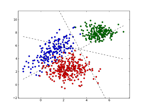
The other major solution component for a production FDC system is a fault model library management capability that can handle large numbers of models. This is necessary because the multivariate approach includes little or no awareness of the physical meaning of the principal components (i.e., they are not “first principles” based), so different operating points for the equipment must have their own sets of fault models. The proper models for a given operating point are selected by matching the values of the “context parameters” for a specific run to those used to store the models. Even if some models can be shared across a range of operating points, the number of distinct models for a foundry megafab will still number in the thousands.

EDA (Equipment Data Acquisition) Standards Leverage

In an advanced fab, there is a spectrum of data collection alternative available for a given application, from basic lot-level summary information to detailed real-time data that can used at the substrate level or even on a die/site basis. For FDC, this spectrum of possibilities is shown in the table below.

SEMI Standard Level

Functionality

Benefit

GEM/GEM300

Fault models difficult to change after initial development if data collection requirements change

Baseline

EDA Freeze I

(1105)

Easy to change equipment data collection plans as fault models evolve and require new data;

Model development environment can be separate from production system

Engineering labor reduction; improved fault models and lower false alarm rate

EDA Freeze II

(0710)

Use conditional triggers to precisely “frame” trace data while reducing overall data collection needs; Incorporate sub-fab component/subsystem data into fault models

Even better fault models; reduced MTTD (mean time to detect) of fault or process excursion; little or no data post-processing required

EDA Common Metadata (E164)

Include standard recipe step-level transition events for highly targeted trace data collection;

Automate initial equipment characterization process by using metadata model to generate required data collection plans

Faster tool characterization and fault model development time

Factory-Specific
EDA Requirements

Incorporate previously unavailable equipment signals in fault models;

Update data collection plans and fault models automatically after process and recipe changes;

Include recipe setpoints in the equipment metadata models

TBD (Not yet applicable)


The left column refers to the level of SEMI standards used to provide the necessary equipment data. The “Functionality” column describes how that data is used in an FDC context, and the “Benefit” column highlights the potential impact these functions can have. 

Let’s say that a fab implemented the capability described on rows 3 and 4 of the table (EDA Freeze II (0710) and E164-compliant EDA Common Metadata). In this case, the process equipment will be able to provide detailed process parameters at recipe step-specific sampling rates sufficient to evaluate “feature extraction” algorithms of even the most demanding FDC models…with context data to select the precise set of models for a given process condition. And even though the specific equipment parameters are necessarily process dependent, much of the software that monitors recipe execution events, generates the data collection plans (DCPs) that provide the trace data, and assembles the context data used by the model management library can be truly generic because of the fab-wide consistency of the equipment interfaces dictated by the E164 standards.

EDApplications4.1

Another aspect of the EDA standards that FDC teams can leverage is the system architecture flexibility enabled by the multi-client capability. Even while a piece of equipment is connected to a production data management infrastructure, the process engineers and statisticians who develop and refine the fault models can use an independent data collection system tailored for process behavior analysis, experimentation, and continuous improvement. When the new fault models are ready for production, the production DCPs can be updated with these new requirements.

KPIs Affected

Accelerate gains, reduce costs

FDC is considered a “mission-critical” application in today’s fabs because of the high cost of unscheduled equipment downtime and the importance of maintaining high product yield. Simply stated, “if FDC is down, the tool is down,” which means that the real-time data collection infrastructure supporting this application is likewise mission critical. As such, improvements in FDC performance can have a major impact on fab performance.

Specifically, FDC directly affects the process yield and scrap rate KPIs through higher fault detection sensitivity, and it affects equipment availability and related KPIs by reducing the number of false alarms that often require equipment to be taken out of production.

So what?

A wise colleague advised me early in my career to always have an answer for this question at the end of every presentation, article, or conversation. To answer this question in financial terms for this posting, let’s consider the cost of FDC false alarms for a production 300mm fab.

Assuming that 

  • an hour of tool time is worth US$2200, a qual wafer costs $250, and an hour of engineering/technician time costs $150, and 
  • it takes 5 hours of tool time, 2 hours of engineering time, and 6 qual wafers to resolve a false alarm, then 

each false alarm costs the company almost $12K. For a fab with 2000 pieces of equipment and an average false alarm rate of 2 per tool per year, that comes to an annual cost of almost $50M! A 50% reduction in the false alarm rate (which is not unreasonable) nets $25M of savings per year. 

Red_smart_factory

If this sounds like “real money” to you, give us a call. We can help you understand how to get on the Smart Manufacturing path with the kind of standards-based data collection infrastructure that is needed to support the latest generation of FDC systems and beyond.


To Learn more about the EDA/Interface A Standard for automation requirements, download the EDA/Interface A white paper today.

Download


Topics: EDA/Interface A, Smart Manufacturing/Industry 4.0, EDA in Smart Manufacturing Series

EDA Applications and Benefits for Smart Manufacturing Episode 3: Real-Time Throughput Monitoring

Posted by Alan Weber: Vice President, New Product Innovations on Mar 28, 2018 11:13:00 AM

In the introduction to this series (posted December 19, 2017), we listed some of the manufacturing stakeholders whose work objectives are directly addressed by the applications we’ll highlight in this and subsequent postings. In the second article, we explained the process used to map the careabouts of key stakeholder groups into specific EDA interface requirements which are can then be directly included in the purchasing specifications. semiconductor wafer

In this post, we’ll explain how some of those interface requirements support an important factory application that has general applicability across all equipment types, namely “real-time throughput monitoring.” This application can realistically work with a variety of equipment types with no custom code or configuration depending, of course, on how faithfully the equipment supplier implements the SEMI standards referenced in the requirements specification. This powerful concept greatly improves the software engineering productivity of a fab’s automation team, so we’ll take some time to explain how this is possible.

Problem Statement

This application addresses the problem of monitoring equipment throughput performance in real time, and raising an alarm when it drifts away from “normal” for any reason. This is especially important for bottleneck equipment (e.g., litho tracks and scanners), because any loss of throughput ripples throughout the line, resulting in lost production and its associated revenue and profit. Stated simply, “lost time on a bottleneck tool can never be recovered.” 

Solution Components

This application requires data that includes primarily the equipment events that chronicle the movement of substrates through the equipment and execution of the recipes appropriate for this equipment type (process, metrology, inspection, sorting, etc.). With this information, the application calculates the process time “on the fly” and compares the current value with the expected (“normal”) value. 

Models_4.pngSmart_Mfg_EDAappsandbenefits_ep3.3.png

This is not as simple as it first may seem, because the expected value will likely depend on the product type, process type, material status, layer, recipe, and several other factors. Taken together, the set of factors that determines “equivalence” of different lots for some processing purpose is called “context.” For this application, the context parameters ensure that you are comparing apples and apples when looking for variations in process time.

EDA (Equipment Data Acquisition) Standards Leverage

By “EDA,” we include not only the standards in the Freeze II / 0710 suite, but also SEMI E164 (EDA Common Metadata), E157 (Module Process Tracking), and by reference, the entire GEM 300 suite. This ensures not only the granularity and breadth of event support necessary to precisely track wafer movement and step-level recipe execution, but also specifies the naming conventions of those events and their associated parameters, regardless of equipment type or vendor.

If the equipment automation purchase specifications include clauses that state “we require that all state machines, states, state transition events, and attributes of the objects defined in the referenced 300mm SEMI standards be implemented and named exactly as specified in the standards,” then all the information you should need to write a truly generic throughput monitoring application will be available on demand.

A robust real-time throughput monitoring algorithm can be implemented with information solely from the following SEMI standards: E90 (Substrate Tracking), E157 (Module Process Tracking), E40 / E94 (Processing / Control Job Management), and E87 (Carrier Management). The Harel state diagrams, events of interest, and EDA metadata model representation* for a couple of these (E90 and E157) are shown in the figures below.

Models_1.png

Models_3.png

Note that as little or as much of the parameter information required to be available for each event (the rightmost picture in each figure) can be collected via the EDA construct of a “Data Collection Plan” (DCP) with one or more “Event Requests.” For more information about these capabilities, consult the SEMI E134 (Data Collection Management) specifications directly, or review some of the extensive educational material available on our web site.

The other point of leverage for the EDA standards is the multi-client capability. This contributes to the productivity and responsiveness of your automation software team members by allowing them to collect and process the data for this application independently from any other application. Specifically, the throughput monitoring functions can be implemented separately from whatever systems host the GEM command and control capabilities, which are usually managed very carefully because of their potentially negative impact on fab operations.

Key ROI Factors

accelerate gains, reduce costsAs we said in the initial post of this series, this application is not just something you could build and deploy with EDA-enabled equipment… in fact, this has already been done, and is delivering real production manufacturing benefit! Specifically, the ROI factors impacted (and benefit delivered) by this application include productivity excursion mean-time-to-detect (MTTD, 50% reduction), selected equipment throughput improvement (3-5%), and overall cycle time reduction (difficult to quantify precisely because of the staged implementation process). 

Of course, these results will vary depending on the manufacturer’s fab loading, operations strategy, and overall automation capabilities, but are representative for leading edge production wafer fabs running at near capacity. However, since these are very common ROI factors, most companies can easily quantify these improvements in real financial terms.

In Closing...

As always, your feedback is welcome, and we look forward to sharing the Smart Manufacturing journey with you.

EDA_apps_benefits_6.png

*The visualizations of equipment metadata model fragments are those produced by the Cimetrix ECCE Plus product (Equipment Client Connection Emulator).

Let us know if you would like to schedule a meeting to learn more:

Schedule a Meeting

Topics: EDA/Interface A, Smart Manufacturing/Industry 4.0, EDA in Smart Manufacturing Series

That's a wrap - SEMICON China 2018

Posted by Kimberly Daich; Director of Marketing on Mar 22, 2018 10:30:00 AM

semichina1.jpgSEMICON China was held from March 14-16, 2018 in Shanghai at the Shanghai New International Expo Centre. Simultaneously co-located at this huge complex were Productronica China and Laser World of Photonics China. All three shows were very busy this year, and it is clear the electronics manufacturing industry in China is booming.
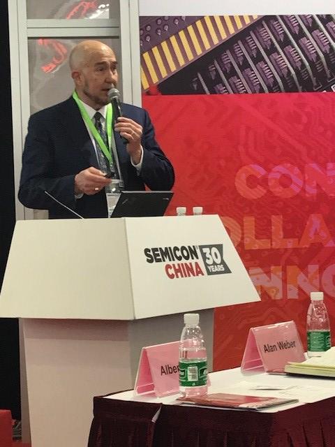
Cimetrix attendees included Dave Faulkner (VP Sales and Marketing), Ranjan Chatterjee (VP Smart Factory Business Unit), Michael Lee (Country Manager Taiwan), Yufeng Huang (Senior Software Engineer), Alan Weber (VP New Product Innovations), and Kimberly Daich (Marketing Manager); Hwal Song (Country Manager Korea) was also able to attend for one day. The Cimetrix booth was busy throughout the show, and provided a comfortable and convenient setting for the many scheduled and walk-in meetings that took place.

Cimetrix partners Facet and Flagship also attended the show, and participated in several customer/prospect discussions. In conjunction with our partner Facet, Cimetrix software products are now used in more than 25 production factories within the China market segment. Moreover, the relationships we have established throughout the semiconductor and electronics markets are strengthening our global presence and enable Cimetrix to provide local support to current and potential clients. The most recent example is our Shanghai office, opened in 2017.

semichina3_alan.jpg

In addition to the exhibitions, SEMICON China sponsored many forums for expert speakers throughout the show. One of these included the New Technology Release Forum where our own Alan Weber was selected as a speaker. His topic “Integrated Equipment Data Collection and Management for Smart Manufacturing” was well received by those in attendance. Smart Manufacturing has been a topic of keen interest at all SEMICONs over the past 18 months, and China was no exception; a separate forum dedicated to Smart Manufacturing drew a standing-room-only crowd to hear a broad range of speakers across the technology spectrum.

We are currently expanding our Shanghai office in response to the exciting growth opportunities we see for our industry in China, and look forward to many years of collaborative work in this region.

Topics: Doing Business with Cimetrix, Events, Global Services, Smart Manufacturing/Industry 4.0

SECS/GEM series: Documentation

Posted by Joe Cravotta, Client Support Engineer on Mar 6, 2018 11:27:00 AM

Case_studies.jpgAs the first article in this Features and Benefits of SECS/GEM series points out, the SECS/GEM standards define a standardized interface that may be used on any equipment. A GEM interface exposes an equipment's capabilities through status variables, data variables, collection events, alarms, data formats, error codes, SECS-II messages, and other optional GEM capabilities. The GEM standard requires each equipment to come with documentation; ensuring a factory has the information it needs to use an equipment’s GEM interface. This documentation is commonly referred to as the GEM manual.

The GEM manual may be distributed in many ways. Currently, most GEM manuals are provided digitally in a Word, Excel, or PDF  document. The vast amount of information in a GEM manual is used to make purchasing decisions, develop host software, and test equipment. For a full GEM interface, the GEM manual must include the following topics: State Models, Scenarios, Data Collection, Alarm management, Remote Control, Equipment Constants, Process Recipe Management, Material Movement, Terminal Services, Error Messages, Clock, Spooling, Control, Supported SECS-II messages, GEM Compliance statement, and Data Item Formats. To keep this post a reasonable length, we will only cover a few of the required topics.

GEM Compliance Statement

The compliance statement is one of the first topics to be reviewed. It is a quick and easy way to understand the features of an equipment’s interface. The manufacturer is required to mark which GEM capabilities are implemented on the equipment, and if they are implemented in a way that is compliant with the GEM standard.

secsgem-documentation-1.png

State Models

State Models is a fundamental GEM capability, and is therefore implemented on every equipment. This capability defines the Communication, Control, and spooling behavior of the equipment. A processing state model must be provided. However, it is not possible to define a processing state machine that can be used on every equipment. The processing behaviors that should be the same for all equipment are specified by the standard. Each state model must be documented with a state model diagram, a transition table, and a text description of every state. The consistent and detailed information about each state model enables a factory to start writing a host application as soon as they have the GEM manual.

secsgem-documentation-2.png

Alarms, Collection Events, Equipment Constants, Data Variables, and Status Variables 

Alarms, Collection Events, and Variables are large components in gathering data from an equipment. It should not be a surprise that these are required to be in the GEM manual. Each alarm on the equipment should have its ID, name, description, and associated Set/Clear events in the GEM manual. The documentation for each collection event should include the ID, name, description, and a list of associated variables. The documentation for all variables will include an ID, name, description, and the data type. Information about a variables default value or value range should also be provided when appropriate. Although not required, it is common to display all this information in five tables that are easy to find. There would be a single table for each of the following: alarms, collection events, equipment constants, data variables, and status variables. See the examples below.

Alarms

secsgem-documentation-3.png

Collection Events

secsgem-documentation-4.png

Status Variables

secsgem-documentation-5.png

Remote Control

Once a factory can gather data from an equipment they start looking at how to control the equipment. Remote Control is the GEM capability that allows a host application to request an equipment to perform an action. Each remote command should be in the manual with its name, description, and details about each command parameter that may be sent with the command. The details of a command parameter should include the name, the format, and a description. An example is shown below.

secsgem-documentation-6.png

SMN and SEDD

GEM manuals rarely come in a format that is easy to parse in software. This often results in duplicating code and making small changes in order to communicate with other equipment. SEMI E172 SECS Equipment Data Dictionary (SEDD) and E173 SECS Message Notation (SMN) are two standards that can drastically increase the flexibility and reusability of a host application. SEDD is an xml file that is easily distributed and parsed in software. SEDD can be considered a modernized GEM manual because it contains much of the same information that is found in a GEM manual. For example, a SEDD file contains details about every variable, collection event, alarm, and supported SECS-II message. A SEDD file uses SMN to represent the data items, variables, and SECS-II messages. SMN is also XML and is the first standard to define a notation for representing data items and SECS-II messages. This means a single application can read a SEDD file, have a short configuration process, and then immediately start using the GEM interface of an equipment. These features allow a single application to be used with multiple equipment instead of creating slightly different variants for each equipment.

Wrap up

The GEM manual is a crucial piece of documentation that is required by the GEM standard to be provided with every equipment. The GEM Manual should be the first place to look for an answer when there is a question about an equipment’s GEM interface. SEMI continues to improve the content and flexibility of a GEM manual by updating existing standards and creating new standards.

Click here to read the other articles in our SECS/GEM Features and Benefits series. 

To download a white paper on an introduction to SECS/GEM, Click below:

SECS/GEM White Paper

Topics: SECS/GEM, Smart Manufacturing/Industry 4.0, SECS/GEM Features & Benefits Series

Cimetrix International, Inc., China; 矽美科国际有限公司,中国

Posted by Yufeng Huang; Software Engineer China on Feb 28, 2018 11:40:00 AM

Yufeng Huang of Cimetrix talks about our China Office Opening. Read now in Chinese or English.

美国矽美科股份有限公司上海代表处成立于2017年8月,地址位于称为中国硅谷的上海张江高科技园区。公司总部(矽美科股份有限公司)创建于1987年,地址位于美国犹他州盐湖城。矽美科公司是一家为半导体行业、SMT行业、PCB行业、光伏行业、LED行业及相关行业的设备制造商和生产工厂提供产品和服务的软件公司。

China_office_1.pngChina_office_2.jpg

矽美科公司有着非常良好的客户评价,公司不仅将自己视为客户的重要供应商,更加将自己视为客户值得信赖的合作伙伴。我们坚信有能力为客户提供全球最先进的基于SEMI标准的软件解决方案。

矽美科上海代表处为中国、台湾等亚太地区客户提供售前产品咨询,客户培训,售后技术支持服务。我很荣幸在今年8月份加入到矽美科上海代表处,在过去的几个月内我们不断收到老客户给予的好评和新客户的合作意向。感谢新老客户对公司的支持,我们将一如既往的为客户提供最优质的、高效的服务,希望我们的产品和服务能让您满足,并为您带来巨大的帮助。

美国矽美科股份有限公司上海代表处
地址:上海市浦东新区盛夏路399弄1号(A座)3楼328室3069单元 (邮政编码201210)
技术联系:黄玉峰
电话:+86-21-8022-0935

销售联系:Michael Lee
电话:+886-926395649


American Cimetrix Incorporated Shanghai Representative Office was established in August 2017. It is located in ZhangJiang High-Tech Park, which is also known as China’s Silicon Valley. The headquarters of Cimetrix, Inc, founded in 1987, is located in Salt Lake City, Utah, USA. Cimetrix is a software company that provides software products and services to OEMs and Fabs in the semiconductor, SMT, PCB, photovoltaic, LED and related industries.

Enjoying excellent customer reputation, Cimetrix considers itself more as customer’s trusted partner than customer’s supplier. We firmly believe that we have the ability to provide customers with the world's most advanced SEMI-based software solutions.

Cimetrix Shanghai Representative Office provides pre-sales consulting, customer training, after-sales technical support services to mainland China, Taiwan and other Asia areas. I am greatly honored to join Cimetrix Shanghai Representative Office in August 2017. In the past few months, we have continuously received favorable comments from existing customers and cooperation intentions from potential customers. Thanks for their trust and support of the company, we will, as always, provide our clients with the best and most efficient services. We believe that our products and services will meet customer satisfaction and greatly enhance your product quality.

American Cimetrix Incorporated Shanghai Representative Office
Address: Unit 3069, Room 328, Floor 3, No. 1 (Block A), Lane 399, Shengxia Road, Pudong New Area, Shanghai (Post Code: 201210)

Technical Contact: Yufeng Huang
Telephone: +86-21-8022-0935

Sales Contact: Michael Lee
Telephone: +886-926395649


Topics: Doing Business with Cimetrix, Global Services, Smart Manufacturing/Industry 4.0

SECS/GEM Series: Alarms

Posted by David Francis: Director of Product Management on Feb 14, 2018 10:30:00 AM

Previous posts have talked about functionality that allows data to be collected through the GEM interface so the factory applications described in the most recent post can analyze this data. With this posting, we return to a discussion of specific features and capabilities of the SEMI E30 GEM (Generic Equipment Model) standard, specifically the management of error conditions on the equipment.

In a perfect world everything goes according to plan, but in reality, things always go wrong. The secret to success is being able to know when something goes wrong, and then responding appropriately.

Minion_alarm.png
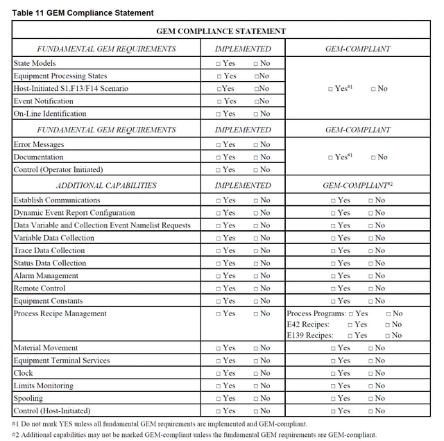
Just like a home alarm system, semiconductor fabs want to know when something bad has happened. They want to prevent the material being processed from being scrapped. Alarm management enables the equipment to notify the host when something goes wrong, and provide information about what has gone wrong. The GEM standard defines Alarm Management as the capability to provide host notification and management of alarm conditions occurring on the equipment. 

In GEM, an alarm is any abnormal situation on the equipment that may endanger people, equipment, or material being processed. For example, if a technician opens an access panel to replace a component, the equipment should send an alarm notifying the host that it is not safe to operate the equipment in its current condition. Another example might be if an equipment requires a high temperature for processing but a sensor detects a low temperature condition, it should trigger an alarm, since running the process under those conditions could damage the material being processed. It is also the responsibility of the equipment manufacturer to inhibit unsafe activities on the equipment when an alarm condition is present. The equipment manufacturer knows best what specific alarms are required on the equipment to ensure safety for people, equipment and material.

Often it is useful to have more information about the conditions in the equipment at the time an alarmflashing-red-light-1.png 
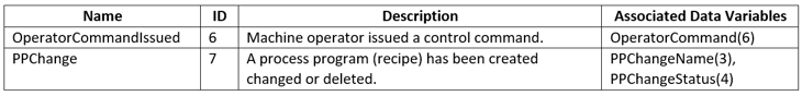
condition occurs. Communicating that additional information to the host is valuable, but cannot be done through the normal Alarm Report Send/Acknowledge messages. To provide a way to get this additional information, GEM requires that two collection events be defined for each possible alarm condition on the equipment – one event for when the alarm is set, and another for when the alarm is cleared. These collection events allow the GEM event data collection mechanisms to be used to send the additional related information to the host when an alarm changes state.

In addition to providing the time of an alarm state change, Alarm Management on the equipment must allow the Host to request a list of all alarm IDs and associated alarm text. The host must also be able to enable/disable individual alarms on the equipment, and query the equipment for the list of alarms that are currently enabled for reporting.

The state diagram for an Alarm is not very exciting, but it fills a vital need. The picture below illustrates the Alarm State diagram:

on-off-switch.jpg

GEM alarms only have 2 states: each alarm is either SET or CLEAR. It’s simple but effective.

Alarm Management isn’t rocket science, but through effective use of Alarm Management, fabs can carefully monitor the health of their process equipment and minimize negative impacts to their production yield. 

Click here to read the other articles in our SECS/GEM Features and Benefits series. 

To download a white paper on an introduction to SECS/GEM, Click below:

SECS/GEM White Paper

Topics: Industry Highlights, SECS/GEM, Smart Manufacturing/Industry 4.0, SECS/GEM Features & Benefits Series