by Rob Schreck
Marketing Manager
As we gear up for SEMICON West, we are encouraged by some good news in the industry after enduring the bleak news of autumn and winter. SEMI reports the North American semiconductor capital equipment industry book-to-bill was over 1.0 in February and March of this year (see Semiconductor Equipment Industry Book-to-Bill), and the PV equipment book-to-bill ratio is starting back up (see PV Manufacturing Equipment Book-to-Bill Increases from Record Low). With the good news comes more companies developing new equipment, drawing more attention to SEMI standards such as SECS/GEM and PV2 (PVECI).
Understanding the SEMI SECS/GEM and PV2 standards, and the impact to their product roadmaps, might seem a little daunting for many equipment suppliers. We have updated a white paper to provide some background, called Introduction to the SEMI Standards: Implementing GEM and PV2.
This paper highlights key elements and issues associated with GEM software projects to help guide users toward a successful implementation.
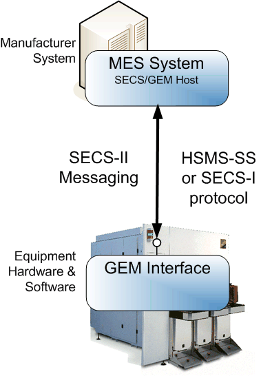
A GEM (E30) interface is implemented by the equipment manufacturer to enable the equipment and factory software (a.k.a. “host”) to communicate using SECS-II (E5) messages via Ethernet.
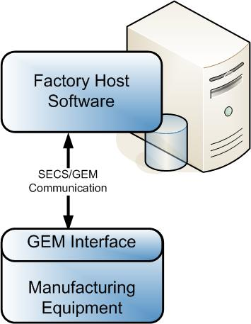
GEM standard compliance consists of fundamental requirements and additional capabilities, and compliance is only required for the equipment interface, not for the factory host software. Companies scale the GEM standard implementations to match the complexity of the equipment and the needs of the factory host software.
The GEM fundamental requirements include establishing communication with the factory host software, implementing a processing state machine, event notification, protocol error messages, and a GEM implementation document. Here is an example of such a document, and you can find a GEM compliance check list at Are You GEM Compliant?
|
GEM COMPLIANCE STATEMENT |
||
|
FUNDAMENTAL GEM REQUIREMENTS |
IMPLEMENTED |
GEM COMPLIANT |
|
State Models |
□ Yes □ No |
□ Yes (see #1) □ No |
|
Equipment Processing States |
□ Yes □No |
|
|
Host-Initiated S1,F13/F14 Scenario |
□Yes □No |
|
|
Event Notification |
□ Yes □No |
|
|
On-Line Identification |
□ Yes □ No |
|
|
Error Messages |
□ Yes □ No |
|
|
Documentation |
□ Yes □ No |
|
|
Control (Operator Initiated) |
□ Yes □ No |
|
|
ADDITIONAL CAPABILITIES |
IMPLEMENTED |
GEM COMPLIANT (see #2) |
|
Establish Communications |
□ Yes □ No |
□ Yes □ No |
|
Dynamic Event Report Configuration |
□ Yes □ No |
□ Yes □ No |
|
Variable Data Collection |
□ Yes □ No |
□ Yes □ No |
|
Trace Data Collection |
□ Yes □ No |
□ Yes □ No |
|
Status Data Collection |
□ Yes □ No |
□ Yes □ No |
|
Alarm Management |
□ Yes □ No |
□ Yes □ No |
|
Remote Control |
□ Yes □ No |
□ Yes □ No |
|
Equipment Constants |
□ Yes □ No |
□ Yes □ No |
|
Process Recipe Management |
□ Yes □ No |
Process Programs: □ Yes □ No E42 Recipes: □ Yes □ No E139 Recipes: □ Yes □ No |
|
Material Movement |
□ Yes □ No |
□ Yes □ No |
|
Equipment Terminal Services |
□ Yes □ No |
□ Yes □ No |
|
Clock |
□ Yes □ No |
□ Yes □ No |
|
Limits Monitoring |
□ Yes □ No |
□ Yes □ No |
|
Spooling |
□ Yes □ No |
□ Yes □ No |
|
Control (Host-Initiated) |
□ Yes □ No |
□ Yes □ No |
GEM Compliance Statement
Much like how the GEM standard is a subset of the SECS-II standard with additional required features, the PV2 standard is a subset of the GEM standard with additional required features, which include:
- The required format to use for data items in the SECS-II messages
- A specific list of variables, equipment constants, and collection events
- A subset of SECS-II messages
- An implementation of SEMI E10 to report equipment states related to reliability, availability, and maintainability (RAM)
- An implementation of the Network Time Protocol (NTP)
- A statement of PV2 compliance
These PV2 requirements should make PV2-compliant equipment even easier than GEM to integrate with the factory host software.


 I have a lot of children—seven. Many of them are still young. Sure it is a lot of fun. However, more often than I like (yet not terribly often since I have really good kids), I get caught in the middle of a “he said/no I didn’t” dispute. That is where one of my children shows up in a huff to wherever I am and reports what “he said”, he meaning another one of my children. Then in the background I’ll hear the other one say either the “no I didn’t’ or the “but that’s because he said” response. And both kids look at me and expect the impartial judge (a.k.a. me) to do something. Each of them will give the impression of complete honesty and full recollection, yet they cannot agree about what happened or about what the other said.