Industry News, Trends and Technology, and Standards Updates

EDATester Product Launch: EDA/Interface A Freeze II Testing

Posted by Jesse Wright; Software Engineer on Jul 25, 2017 11:30:00 AM

In a world of automated equipment, having tools to automate the testing of an equipment’s implementation of the SEMI EDA (Equipment Data Acquisition) standards (also known as Interface A) is invaluable. Cimetrix is proud to announce an integrated solution that supports the broadest range of use cases in EDA/Interface A testing - the Cimetrix EDATester™. EDATester is a tool that will help organize, streamline, and automate the testing process while also providing other analytical capabilities. 

Cimetrix knows that testing an equipment interface is not simply a one-time event; rather, tests should be performed in the OEM’s facilities throughout the development process and before final shipment, upon delivery to the customer’s factory, and even after the equipment has been placed into full production. Cimetrix EDATester is designed to do exactly that.

EDATester4.png

What do we really mean by “testing?” What are we testing? Since the scope is very broad, let's frame the answer in a few distinct categories.

Compliance Testing

Does the equipment’s EDA interface behave correctly based on the SEMI E120, E125, E132, and E134 standards and all the services defined therein? To answer this question, we make use of the ISMI EDA Evaluation Method. This document contains a set of functional evaluation procedures that “tests” the equipment’s implementation of the standards. These procedures check for things like ACL privileges and roles, establishing and terminating communications sessions, managing (or preventing the management of) Data Collection Plans (DCPs), and even looking for the proper notification of metadata revisions. If everything works as expected in these procedures, that equipment would be deemed “compliant.”

EDATester uses ISMI’s functional evaluation procedures as guidelines, and implements tests that are automated for all client-side actions. A process that might have taken multiple days to execute manually can be done in minutes, even when some interaction with the equipment itself is required; the fully automated tests that require no user interaction with the equipment can be run in seconds.

Performance Testing

Everything might look great on the client side with the ability to define a DCP, activate it, and start receiving data; but how many DCPs will the equipment actually support? How fast can I sample the parameters I want to collect in my Trace Requests without overloading the equipment’s EDA interface? Even if I could do this manually, how would I begin to answer this question?

EDATester automates multiple iterations of performance testing using different variations of DCPs while analyzing the timestamps of the E134NewData messages to determine the integrity of the actual sampling rate. Having such tests helps you determine whether the equipment can handle a new DCP in response to a process engineering request, or if the equipment supports the full range of performance requirements agreed to in the purchasing specifications. To this end, you can specify testing configurations for things such as:

  • Number of simultaneously active DCPs 
  • Trace Request Sampling Interval
  • Number of parameters per Trace Request
  • Group Size for message buffering
  • Timing tolerance for expected vs. reported Data Collection Report (DCR) timestamps

Conformance Testing

The testing tool in practical use across the industry for measuring an equipment’s conformance to the SEMI E164 EDA Common Metadata standards is called the Metadata Conformance Analyzer (MCA). It uses a set of .xml files describing the metadata model as input, analyzes the model according to the requirements of E164, and provides feedback.

EDATester currently generates the .xml input model files required by the MCA, and may eventually incorporate the model conformance testing functions as well.

Summary

Having the correctly sized wrench when you need to apply the proper torque to a bolt is helpful and sometimes necessary—at least you can get the job done. But when you have hundreds of bolts to insert and tighten precisely, wouldn’t you rather have an adjustable ratchet? Or an air ratchet?

Whether it’s to test and characterize the EDA interface on a new equipment type,  verify that a software update to a production piece of equipment has been installed correctly, or debug an interface performance issue that has somehow arisen in production, the Cimetrix EDATester is the right tool to have in your arsenal to quickly, effectively, and thoroughly “test” an equipment’s EDA interface capabilities. Don’t waste another day with manual processes that leave you guessing. Get in touch with us today to find out more about the EDATester product. 

Topics: EDA/Interface A, Cimetrix Products

Implementing CIMPortal Plus

Posted by Derek Lindsey: Product Manager on Jul 7, 2017 12:07:00 PM

Toolkit.jpg

Generally, when I do a DIY (do-it-yourself) project around the house, I spend the majority of the time searching for my tools. The other day I was helping a friend with a project. He had a well-organized tool box and it seemed that the perfect tool was always at his fingertips. I was amazed at how fast the project went and how easy it was when the right tools were handy.

In April of 2016, we published a blog called OEM EDA Implementation Best Practices that outlined ten things to consider when designing an equipment-side EDA / Interface A solution to fit your needs. This blog post analyzes a few of those recommendations and looks at how using the Cimetrix EDA products CIMPortal Plus, ECCE Plus and EDATester (a well-stocked and organized tool box) makes it very easy to follow those recommendations.

The basic steps in creating a useful EDA implementation are:

  1. Determine which data will be published
  2. Build an equipment model
  3. Deploy the model
  4. Publish the data from the equipment control application
  5. Set up a data collection application
  6. Test the interface

The blog post mentioned above states, “Since the content of the equipment metadata model is effectively the data collection contract between the equipment supplier and the factory users, your customer’s ultimate satisfaction with the EDA interface depends on the content and structure of this model.” Before building your model, you need to determine what data the equipment will make available for collection. CIMPortal Plus has the concept of a Data Collection Interface Module (DCIM) that publishes this data to the EDA server. The engineer building the model will map the data from the DCIM into the equipment model.

Once the mapping of the data is complete, the engineer will need to put this data in a format understood by the server. CIMPortal Plus provides a utility called Equipment Model Developer (EMDeveloper – pictured below) that makes it easy to create the hierarchy of your equipment (SEMI E120) and embed the data from the DCIM into that model (SEMI E125). If you use the tools and best practices provided in EMDeveloper, your equipment model will conform to the SEMI E164 (EDA Common Metadata) standard as well. This can be very useful when writing data collection applications so conformance to E164 is being required by more and more fabs. The E164 standard was developed to encourage companies using Interface A connections to provide a more common representation of equipment metadata based upon the SEMI E125 Specification for Equipment Self-Description. This makes data collection more uniform across these pieces of equipment.

CIMPortalPlus_Blogimage1.png

Once the model is created and validated, it is deployed to the CIMPortal Plus server. The server is the component that manages and tracks all data collection plans, reports, tasks, access control and timing. 

With the DCIM information embedded in the model (described above), it is easy for the equipment control application to push the data to be published to the EDA server for collection. This is done by using a simple API available on the DCIM interface.

In addition to CIMPortal Plus server capabilities, Cimetrix has other products available to help with client-side data collection. ECCE Plus is an industry approved method for manually testing EDA implementations. For users who need to create client-side data collection applications, Cimetrix also provides EDAConnect - a powerful library that handles all the connection details and allows developers to concentrate on the specific data collection and analysis tasks.

Fabs receive a wide variety of equipment with EDA implementations from numerous vendors. They want to use a single verification application to make sure that all EDA implementations are compliant to the EDA standards. That’s where EDATester comes in. EDATester is a new product that allows users to quickly and accurately verify EDA standards compliance by automating the test procedures ISMI EDA Evaluation Method that were defined specifically for this purpose. If you use Cimetrix products to implement your EDA interface, you are guaranteed to be compliant with the SEMI EDA standards. But whether you use Cimetrix products to implement your EDA interface or not, you (and your fab customer) want to rest assured that your implementation is fully compliant. Moreover, you’ll want to know that you’ve met the fab’s performance criteria for your equipment interface. To support this use case, the EDATester also allows users to quickly profile the performance of EDA data collection on a piece of equipment so that fabs and those using the data will know the boundaries within which they can successfully collect equipment data.

With the well-stocked EDA tool box provided by Cimetrix, following the EDA best practices in creating an efficient, standards-compliant EDA interface becomes a snap.

Topics: EDA/Interface A, Cimetrix Products

CCF Series Wrap-up

Posted by Derek Lindsey: Product Manager on Apr 12, 2017 11:00:00 AM

One of the habits outlined in Stephen R. Covey's book, The 7 Habits of Highly Effective People, is to "Begin with the End in Mind." He goes on to explain that beginning with the end in mind means to "begin each day, task, or project with a clear vision of your desired direction and destination, and then continue by flexing your proactive muscles to make things happen.”

Beginning an equipment control project with a clear vision of your desired destination makes it much more likely that you will have a successful project. A blog post titled CIMControlFramework Work Breakdown dated March 15, 2016 outlined the tasks necessary to create a first-class equipment control application using CIMControlFramework (CCF). Since that initial blog post, Cimetrix has explored each of the tasks labeled in the work breakdown structure in greater depth in their own blog posts as follows:

Looking back from the successful completion of a CCF equipment control application makes it clear that the work breakdown vision from the beginning helped gain that success.

You can also reference the following blog posts related to CimControlFramework:

CIMControlFramework Dynamic Model Creation

Learning from Others

Build vs. Buy

WCF and CIMControlFramework

To learn more about CCF, visit the CIMControlFramework page on our website!

Topics: Equipment Control-Software Products, Cimetrix Products

Testing Your CCF Application without Waiting for Hardware

Posted by Brent Forsgren on Mar 29, 2017 11:26:00 AM

You've heard the expression, “you can’t make an omelet without breaking a few eggs.” That is, you shouldn't be surprised if you end up destroying a few things in the process of achieving your goal. When it comes to building a new piece of equipment, do you really want to risk breaking a few wafers, or worse yet, hurting personnel or equipment, to develop your new tool control software? I think everyone would answer with a resounding “No!”
In the March 2016 blog post on CIMControlFramework Work Breakdown, simulation was listed as one of the eleven points to be taken into consideration when developing an equipment control application using CIMControlFramework (CCF). In addition to personnel and hardware safety, there are other reasons to use simulation when developing equipment control applications, namely:

  • You want to start testing your software as early as possible, often this is before your equipment is finished. Then when your equipment is ready, integrating your tested software with your hardware will proceed smoothly and minimize delays in your time to market.

  • If you have an existing tool and you’re upgrading your tool control software, scheduling software testing time while still allowing other engineering teams (mechanical, process, etc.) to get their jobs done is challenging.

  • The hardware components that comprise your tool, e.g. robots, load locks, and process modules, will not be finished at the same time. You want to test your software with real hardware as soon as possible, while still simulating the missing equipment components.

  • Tool time is valuable. It's nice to be able to test your software without using the valuable tool time where possible.

  • It is likely that your tool will have more than one configuration, customized for each of your clients. Setting up different hardware configurations in order to develop and test your tool control software is time consuming. You want to be able to test your software for all of your equipment configurations in timely manner.

Wafer_tool-CCF-Simulator.jpgCCF provides a simulator that you can use to test your tool control software during development, and before you run the software on the real hardware. Running against a simulator first will expose issues in your software without damaging people, material and hardware. CCF’s simulator simulates real hardware, which means it is not necessary to add conditional checks in your software to check when it is running with a simulator versus real hardware.

CCF’s simulator features include:

  • Simulation of atmospheric and vacuum hardware components, e.g. load locks, vacuum pumps, vacuum gauges, etc.

  • Simulating delivery and removal of carriers to load ports, both manually and automatically using E84 handshaking.

  • Simulation of robot moves for both atmospheric and vacuum robots.

  • Simulation of I/O.

  • Simulation of hardware faults, to safely test error handling.

  • Simulate running single jobs or cycling wafers for endurance testing.

Additionally, CCF provides other tools to help you test your software without hardware.  CCF provides a Visual Studio template, and a number of classes and interfaces to aid you in developing simulation software for your process module or other custom hardware. Use the Visual Studio template to start development of GUI user controls for simulated hardware. Implement CCF’s I/O simulation interfaces for generating inputs to your tool control software and writing outputs to your simulated hardware. Tie the two sides together using CCF’s simulation client and server to handle the communication.

With these CCF tools, you can develop and test your tool control software without hardware. When hardware is available, you can test your software with your tool with a high degree of confidence that it will perform as expected.

Avoid “breaking a few eggs” and develop your tool control software with CCF and test it using CCF simulation features.

To learn more about CCF, visit the CIMControlFramework page on our website!

Topics: Equipment Control-Software Products, Cimetrix Products

Using CCF I/O Helper Functionality

Posted by David Warren: Director of Software Engineering on Mar 14, 2017 12:00:00 PM

“Can you hear me now?”

A Cimetrix blog post on March 15, 2016 entitled “CIMControlFramework Work Breakdown”mentions that CIMControlFramework (CCF) includes ASCII serial drivers and IO providers.  What does that mean and why should you care?

Factory Automation Software
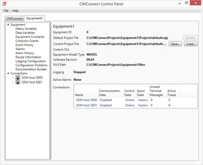
Equipment automation is all about creating software that controls hardware—combining individual components into a harmonious whole, with each piece playing its own unique part.  A critical aspect of control is the ability to communicate—and that is where CCF’s ASCII serial driver and IO providers can help you create your equipment application.

The .NET Framework, like many software development platforms, provides built-in support for serial ports and TCP/IP ports.  This built-in support is great for low-level, binary communication, but hardware devices often just need a simple ASCII connection.  For such hardware, CCF’s ASCII serial driver frees you from worrying about the connection and the underlying implementation.  You can focus on the content of the message instead of the mechanics of delivery.  It’s like using a telephone—you want to focus on the conversation rather than worrying about how the sounds are transmitted between the phones. 

Another common class of hardware uses signals to communicate.  These signals can be as simple as only having two possible values (think “on” and “off”) or having a range of values, like a temperature.  Each signal also has a direction—it is either an input or an output.  For input signals, the value is determined by the hardware and read by the software.  Output signal values are determined by the software and sent to the hardware.  For example, control software might use an output signal to turn a light on and off, and an input signal from a photocell to verify the light is on or off.  This class of hardware is called I/O (short for input/output) devices and is supported by CCF.

CCF includes support for communicating with ASCII serial and I/O devices to make your job easier.  Don’t spend your time and effort asking the hardware “Can you hear me now?”  Use CCF and focus on combining the parts into the harmonious whole. 

To learn more about CCF, visit the CIMControlFramework page on our website!
Topics: Equipment Control-Software Products, Cimetrix Products

Storing Data in a CCF application

Posted by Derek Lindsey: Product Manager on Mar 8, 2017 1:00:00 PM

In Sir Arthur Conon Doyle’s A Scandal in Bohemia, Sherlock Holmes tells Watson, “It is a capital mistake to theorize before one has data. Insensibly one begins to twist facts to suit theories, instead of theories to suit facts.”

In a March 2016 blog post on CCF work breakdown Cimetrix listed eleven points to be taken into consideration when starting an equipment control application using CIMControlFramework (CCF). One of the tasks in the work breakdown is to determine what kind of data collection and storage is to be used in your CCF application and determine how that data is to be stored.

User_Interface_Sm_CCF_1-5-17.jpg

CCF provides several mechanisms for collecting and storing data. These include:

  • History Objects

  • Full GEM Interface

  • Full EDA/Interface A Interface

  • Centralized DataServer

The remainder of this blog post will look at each of these items in more detail.

History Objects

In early iterations of CCF, users noticed when using logging, there were certain messages that they wanted to be able to query without the overhead of having to search all log messages. To help accommodate this need, History objects were introduced. Some examples of these objects in CCF are EPT History, Wafer History and Alarm History. When an important event happens in the life of a history object, a log message is written to a database table (configured during CCF installation) that corresponds to that type of object. That database table can be queried for the specific historical information for only that type of data. 

Full GEM/GEM 300 Interface

As described in a CCF blog post from February 15, 2017, CCF comes standard with a fully implemented GEM and GEM 300 interface. The GEM standards allow users to set up trace and event reports for the collection of GEM data. No additional programming is required by the application developer to have access to the GEM data collection.

Full EDA/Interface A Interface

The same blog post of February 15th also states that CCF comes standard with a fully implemented Freeze II and E164 compliant EDA interface. EDA can be used to set up data collection plans based on Events, Exceptions and Traces. With the E157 standard and conditional trace triggers, EDA makes it easy to zero in on the data you want without having to collect all data and then sift through it later.

Centralized DataServer

In order to create, initialize, populate and pass data, CCF uses a centralized DataServer object. The DataServer is responsible for creating the dynamic EDA equipment modelas well as populating CIMConnect with Status Variables, Data Variables, Collection Events and Alarms. All this is done at tool startup so that the data available exactly matches the tool that is in use.

Data is routed to the DataServer which then updates the appropriate client – such as EDA, GEM or the Operator Interface. An equipment control application can register to receive an event from the data server when data changes. Users can key off of this event to capture that data and route it to a database as desired. Since all tool manufacturers have different requirements for which database to use and how data is written to that database, CCF leaves the actual SQL (or equivalent) commands for writing the data to the equipment application developer.

With CCF Data collection and storage is … Elementary.

To learn more about CCF, visit the CIMControlFramework page on our website!

Topics: SECS/GEM, EDA/Interface A, Equipment Control-Software Products, Cimetrix Products

CCF Provides Fully Implemented GEM300 and EDA Interfaces

Posted by Bill Grey: Distinguished Software Engineer on Feb 15, 2017 1:00:00 PM

What does this mean and why should I care?

The SEMI standards for 300mm Semiconductor Manufacturing Equipment can be an overwhelming burden of information to understand, let alone implement.

The GEM standards comprise over 450 pages of documentation: E4, E5, E30, E37, E37.1, E172, E173.

The 300mm standards add another 280 pages: E39, E40, E87, E90, E94, E116, E157, E148.

And the EDA standards pile on an additional 480 pages: E120, E125, E128, E132, E134, E138, E164.

That’s over 1200 pages of standards documents filled with requirements and implementation information. 

On top of that GEM and EDA collect data differently from the equipment.  See a post we did on data collection for more information on those differences.

Implementing the requirements defined in those standards without an SDK would be a very brave undertaking.  Even with SDKs for the standards, it would be a fair amount of work, when all you really want to do is get your equipment automated.

In addition, it is very important that those standards be implemented correctly in order for your equipment to be smoothly integrated and accepted into each fab.  Different fabs use the standards slightly differently or have additional requirements.   This requires experience.

GEM300 and EDA standards implementation is a very large burden.

semi standards difficult burden

So what does this mean?

One of the large tasks for the EDA standards is defining a hierarchical model of the equipment and what data it can produce in XML per the schemas defined in the standards.   Creating the initial model and keeping it up to date as the equipment evolves is a tedious task.  In addition, that model must be conformant to the E164 standard (which has over 10 pages of requirements on its own).   See our blog post on conformance testing. CCF does this for you, producing an E164 compliant EDA model in the background based on your CCF programming. See our blog post on CCF dynamic model creation further details.  CCF also builds the GEM interface model for you at the same time.

Further, CCF is completely GEM compliant and 300mm compliant, using the Cimetrix CIMConnect and CIM300 products which have been successfully deployed in every 300mm fab around the world on many different equipment types.

Twelve hundred pages of standards, compliantly implemented, at no additional effort.  That is what this means.

Turn that donkey into a goat and use CCF.

To learn more about CCF, visit the CIMControlFramework page on our website!


Topics: SECS/GEM, Equipment Control-Software Products, Cimetrix Products

Implementing your Process Module Using CCF

Posted by Tim Hutchison: Senior Software Engineer on Feb 9, 2017 12:30:00 PM

You have designed the ultimate process that will revolutionize the semiconductor industry.  The parts have been collected, the process module assembled.   But now you need the software to make all the components work together.

As described in a recent CIMControlFramework (CCF) blog post around designing recipes, the recipe is the secret sauce for your process.  The recipe is used to direct the hardware to perform the process; How much time in a step, temperature, gas flow, pressure, etc.

The recipe provides directions to the process module on how to perform the processing.  How and when to enable/disable hardware components.  What setpoints to be set for components.  How much time to spend on any given step.  The process module (PM) software that you develop will take the recipe that you have defined and perform the operations using that recipe. CCF stays out of your way to allow to create your secret sauce.  

CCF makes integrating your process module easy.  CCF provides a simple process module interface that allows CCF to know when to prepare for processing, prepare for transfer, and process using the supplied recipe.

 Your process module hardware may be made up of any number and types hardware components, E.g.  Mass Flow Controller(s), valves, chuck, etc. that will be used to process the recipe. Since CCF does not use proprietary interfaces and does use C# and Visual Studio, creating interfaces to your hardware is much easier and left to you to design and develop these drivers. CCF makes it easy to connect to your hardware, whether it is via a PLC or talking directly to the hardware. 

CCF makes it incredibly simple to report data to a UI, a GEM host and even an EDA client.  Declare your status variable, update, and publish.  The data is reported to all three for you automatically!!

CCF takes the stress out of the necessary evil of moving material through the equipment to get it to your process module. It provides an interface for interacting with your process module allowing you to spend your time where it matters most - creating your secret sauce to help make you successful!

To learn more about CCF, visit the CIMControlFramework page on our website!
Topics: Semiconductor Industry, Equipment Control-Software Products, Cimetrix Products

EDA Testing – How is this accomplished today??

Posted by Alan Weber: Vice President, New Product Innovations on Feb 7, 2017 1:30:00 PM

Over the past several months, we have posted a number of blogs dealing with the testing of SEMI’s Equipment Data Acquisition (EDA / aka Interface A) standards suite. The first of these posts connected the importance of this topic to the increased adoption of the EDA standards across the industry, and broke the overall problem domain into its three major components. 

Subsequent postings provided additional detail in each of these areas:EDA_Icon.png

To bring this series to a close, this post addresses the “as-is” state of EDA testing as it is practiced today by the advanced semiconductor manufacturers who are requiring EDA interfaces on new equipment purchases and the suppliers who provide that equipment. 

For compliance testing, the three options in general use include: 

  1. ECCE Plus product- this software tool was originally developed under contract with the International Sematech Manufacturing Initiative (ISMI) to validate the fidelity, usability, and interoperability of early versions of the standard; it can used to manually execute a set of procedures documented in the “ISMI Equipment Data Acquisition (EDA) Evaluation Method for the July 2010 Standards Freeze Level: Version 1.0” document (see title page below) to exercise most of the capabilities called for in the standard; note that this is the only commercially available solution among the three.

ISMI.png

  1. Company-specific test suites – one major chip manufacturer (and early adopter of EDA) maintains its own partially-automated set of compliance tests, and provides this system to its equipment suppliers as a pre-shipment test vehicle. This set of tests is then used in the fab as part of the tool acceptance process; however, this system also includes a number of company-specific automation scenarios, which are not available for outside use. This highlights the need to support custom extensions in an industry-validated tester if it is to be commercially viable.

  2. In-house custom test clients – this is a variation of #2 that some of the major OEMs have chosen as their economies of scale dictate; the problems with this approach are that a) the test clients must be kept current with the EDA standards, which are themselves a moving target, and b) unless thoroughly validated by the eventual customers of the equipment, there is no guarantee that passing these tests will satisfy the final acceptance criteria for a given factory. 

For performance and stability testing, there are no automated solutions currently available. The ISMI EDA Evaluation Method does describe some rudimentary performance evaluation procedures, but these no longer reflect the expectations of the customers with many years of accumulated EDA production experience. Clearly a better solution is needed.

Finally, for metadata model conformance testing, the only available solution is the Metadata Conformance Analyzer (MCA) that was commissioned by Sematech and implemented by NIST (National Institute of Standards and Technology). It has not been updated in almost five years, and exhibits a number of known issues when applied to a SEMI E164-compliant equipment model (E164 = Specification for EDA Common Metadata), so it will be increasingly insufficient as more companies require full Freeze II / E164 specification compliance. 

The good news in all this is that Cimetrix has recognized and anticipated this emerging need, and is actively addressing it on our product roadmap. If you want to know more about EDA testing and/or discuss your specific needs, please contact Cimetrix for a demonstration of this exciting new capability!

Topics: EDA/Interface A, Data Collection/Management, Cimetrix Products, EDA Testing Series

Designing Recipes in CCF

Posted by Derek Lindsey: Product Manager on Jan 24, 2017 11:00:00 AM

Anyone above a certain age will be able to tell you what you get when you combine two all-beef patties, special sauce, lettuce, cheese, pickles, onions – on a sesame seed bun. There are many who would argue that what sets a Big Mac apart from other burgers – and has made it one of the best-selling products of all time – is the special sauce.

In a March 2016 blog post, Cimetrix listed eleven points to be taken into consideration when starting an equipment control application using CIMControlFramework (CCF). One of the things to consider is how you want to provide process and path information through the tool using recipes. This blog post delves a little deeper into the recipe aspect of equipment control applications.

In CCF, recipes are either process recipes or sequence recipes.

Cookbook1.png

A process recipe contains the instructions to be carried out by a particular process module. These instructions can range from temperature settings to types of gas to flow. The most important aspect of any tool control application is allowing the tool manufacturer to do what they do best – perform their process better than anyone else in the world. The process recipe allows tool manufacturers to add their special sauce to the wafer. CCF provides a sample process recipe implementation as well as very simple process recipe editor. Since recipes are generally custom for each tool manufacturer, CCF application developers usually want to customize the recipe contents for a process recipe.

If the processing of material is the special sauce, the rest of the application, moving the wafer through the tool, is a necessary evil. To assist in moving material through the tool, CCF also provides a sequence recipe. A sequence recipe determines which process recipes are to be run, at which modules to run them, and the order in which this is to occur. CCF provides a sample sequence recipe editor that can be used in creating sequence recipes or customized for each tool manufacturer’s needs.

Both process and sequence recipes can be created on the tool or downloaded from a factory host. CCF provides a handler that receives recipes from the host and stores them in the Recipe Server. Regardless of where the recipes are created, CCF’s Recipe Server stores the recipes locally and passes them in to the scheduler when a job is to be run. The Recipe Server allows recipes to be stored as Engineering recipes while they are being finalized. They can then be promoted to Production recipes for use in a production environment. 

By making use of recipes in CCF, you can ensure that your special sauce is applied to material processing to help make your tool one of the best-selling in history.

To learn more about CCF, visit the CIMControlFramework page on our website! 

Topics: Equipment Control-Software Products, Cimetrix Products