In the EDA Best Practices blog series, we have discussed choosing a commercial software platform, using that package to differentiate your data collection capabilities and how to choose what types of data to publish. In this post we will review why you should choose to provide an E164-compliant equipment model.
What is E164?
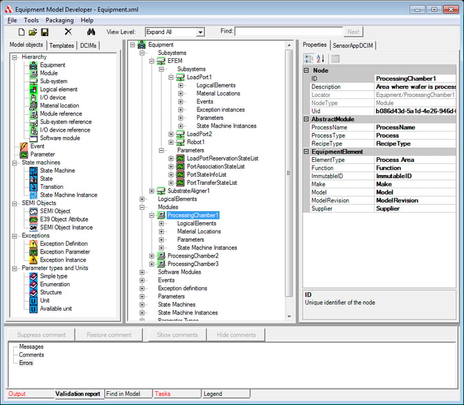
Equipment Data Acquisition (EDA) - also referred to as Interface A - offers semiconductor manufacturers the ability to collect a significant amount of data that is crucial to the manufacturing process. This data is represented on the equipment as a model, which is communicated to EDA clients as metadata sets. The metadata, based upon the SEMI E125 Specification for Equipment Self-Description, includes the equipment components, events, and exceptions, along with all the available data parameters.
Since the advent of the SEMI EDA standards, developers and fabs have recognized that equipment models, and the resulting metadata sets, can vary greatly. It is possible to create vastly different models for similar pieces of equipment and have both models be compliant with the EDA standards. This makes it difficult for the factories to know where to find the data they are interested in from one type of equipment to another.
Recognizing this issue, the early adopters of the EDA standards launched an initiative in to make the transition to EDA easier and ensure consistency of equipment models and metadata from equipment to equipment. This effort resulted in the E164 EDA Common Metadata standard, approved in July 2012. Another part of this initiative was the development of the Metadata Conformance Analyzer (MCA), which is a utility that tests conformance to this standard. With this specification, equipment modeling is more clearly defined and provides more consistent models between equipment suppliers. This makes it easier for EDA/Interface A users to navigate models and find the data they need.
Power of E164
The E164 standard requires strict name enforcement for events called out in the GEM300 SEMI standards. It also requires that all state machines contain all of the transitions and in the right order as those called out in the GEM300 standards. This includes state machines in E90 for substrate locations and in E157 for process management. The states and transition names in these state machines must match the names specified in the GEM300 standards.
These requirements may seem unnecessarily strict, but implementing the common metadata standard results in:
- Consistent implementations of GEM300
- Commonality across equipment types
- Automation of many data collection processes
- Less work to interpret collected data
- Ability for true “plug and play” applications
- Major increases in application software engineering efficiency
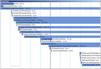
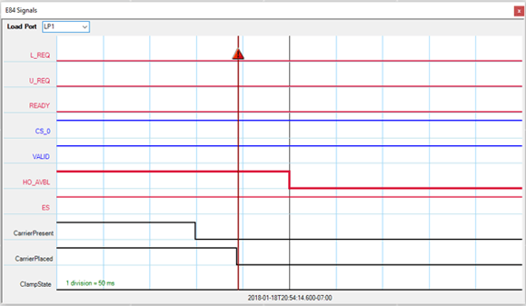
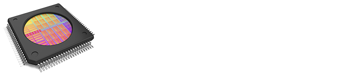
Knowing that a model is E164 compliant allows EDA client applications to easily and programmatically define data collection plans knowing that the compliant models must provide all of the specified data with the specified names. For example, the following application is able to track carrier arrival and slotmap information as well as movement of material through a piece of equipment and process data for that equipment.
This application will work for any GEM300 equipment that is E164 compliant. The client application developer can confidently create data collection plans for these state machines, knowing that an E164-compliant model must provide the needed state machines and data with the proscribed names.
Decide to be E164 compliant
A number of leading semiconductor manufacturers around the globe have seen the power of requiring their equipment suppliers to provide EDA/E164 on their equipment, and now require it in their purchase specifications.
If you are a semiconductor manufacturer, you should seriously consider doing the same because it will greatly simplify data collection from the equipment (and most of your candidate suppliers probably have an implementation available or underway.
If you are an equipment supplier and your factory customers have not required that your EDA models be E164 compliant, you should still seriously consider providing this capability anyway as a way to differentiate your equipment. Moveover, E164-compliant models are fully compliant with all other EDA standards. Finally, it is much easier and more cost effective to create E164-compliant models from the outset than it is to create non-compliant models and then convert to E164 when the factory requires it.
Conclusion
The purpose of the E164 specification is to encourage companies developing EDA/Interface A connections to implement a more common representation of equipment metadata. By following the E164 standard, equipment suppliers and factories can establish greater consistency from equipment to equipment and from factory to factory. That consistency will make it easier and faster for equipment suppliers to provide a consistent EDA interface, and for factories to develop EDA client applications.

 The old adage “You get what you pay for” doesn’t fully apply to equipment automation interfaces… more accurately, you get what you require, and then what you pay for!
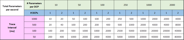

 Cimetrix just finished exhibiting at SEMICON Southeast Asia for the first time. And a grand entrance it was. Located in Kuala Lumpur, Malaysia, this is one of the regional SEMICON shows put on by SEMI, a global industry association serving the manufacturing supply chain for the electronics industry. Southeast Asia is a hotbed for semiconductor backend and PCBA (SMT) industries. With our new employee Raymund Yeoh located in Penang, Malaysia; combined with our distribution partner Electrotek based out of Singapore, Cimetrix now has a strong presence to support Industry 4.0 adoption in Southeast Asia.
  By working closely with SEMI, Cimetrix had a new booth in the SEMI Smart Manufacturing Pavilion and an impressive demonstration in the SEMI Smart Manufacturing Journey.
 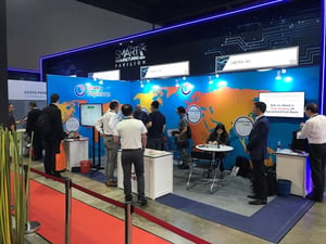 Our booth was extremely busy the whole time with demonstrations of Sapience and EquipmentTest. We gave out vouchers for free copies of
 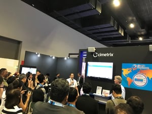 Here is Mike and Jesse giving a demonstration to a tour group. The equipment is located right behind the crowd for all to see; with Sapience displaying data and the crowd taking pictures. SEMI did a great job organizing this. We had top government officials, factories, equipment manufacturers, electronics distributors and universities come through the tours. We also exceeded expectations by adding artificial intelligence to the demonstration. Amazon Alexa was integrated into Sapience which allowed us to ask Alexa which factory was most productive last week. Alexa and Sapience analyzed the data and gave the answer to the tour crowd.


 The automation requirements for the most advanced fabs call for the latest versions (Freeze II) of all the standards in the EDA suite, including the EDA Common Metadata (E164) standard. Dealing with older versions of the standard in the factory systems creates unnecessary work and complexity for the fab’s automation staff, so it is best to implement the latest versions from the outset. The Cimetrix CIMPortal Plus product makes this a straightforward process using the model development and configuration tools in its SDK (Software Development Kit), so there is absolutely no cost penalty for providing the latest generation of standards in your interface.
  This is why the most advanced fabs have been far more explicit in their automation purchase specifications with respect to equipment model content, going so far as to specify the level of detailed information they want to collect about process performance, equipment behavior, internal control parameters, setpoints and real-time response of common mechanisms like material handling, vacuum system performance, power generation, consumables usage, and the like. This level of visibility into equipment operation is becoming increasingly important to achieve the required yield and productivity KPIs (Key Performance Indicators) for fab at all technology nodes.
  Before the fab’s automation team can fully integrate a new piece of equipment, it must follow a rigorous acceptance process that includes a comprehensive set of interface tests for standards compliance, performance, and reliability. This process is vital because solid data collection capability is fundamental for rapid process qualification and yield ramp that shorten a new factory’s “time to money.” If you know what acceptance tests and related software tools the fab will use (which is now explicit in the latest EDA purchase specifications), you can purchase the same software tools, perform and document the results of these same tests before shipping the equipment.
 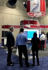 Cimetrix features the latest in Smart Factory and Equipment Connectivity technology. For the show this year, we chose to upgrade our booth space, allowing us to have more meeting room within the booth as well as several prominent demo stations in each corner. We also featured a popular Virtual Reality station in our booth. We brought a great team of ten to the show this year to staff the booth, give demo’s and greet the many attendees who stopped by throughout the 3 day expo.