 As an OEM, implementing GEM on your equipment can seem like a daunting task. However, as GEM gains popularity in your industry, your customers may start requiring your equipment to be “GEM Compliant”.
So, what does it take to implement GEM on your equipment and become “GEM Compliant”? To answer this question, let’s first understand GEM.
Officially titled the “Generic Model for Communication and Control of Manufacturing Equipment,” GEM is a SEMI standard (E30), which defines standard methods to communicate with host software for monitoring and/or controlling purposes. Essentially, GEM provides a common language for a host system to communicate with the various equipment in a factory.
Next, let’s understand why customers are demanding your equipment to be GEM Compliant.
As industry trends such as Industry 4.0, Smart Factory, and Big Data drive data exchange and process automation in manufacturing, factories desire to connect each machine to their network for data collection and control. Essentially, factory equipment is added to the “Internet of Things” – also called IIOT - Industrial Internet of Things.
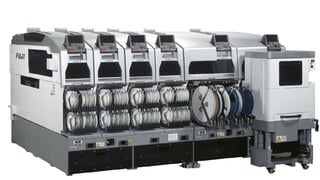
GEM is a powerful enabler for factories to implement these industry trends. A factory no longer needs to develop disparate/custom interfaces to communicate with different equipment types. A factory can develop common applications to communicate to all equipment via a single common GEM protocol. Originally, GEM was widely adopted in the Semiconductor Front End industry followed later by the Photovoltaic and LED industries. Recently the PCB industry selected GEM as their standard. And GEM is quickly gaining adoption in other electronics industries such as Semiconductor Back End, Flat Panel Display, and Surface Mount Technology.
By connecting GEM equipment, factories can immediately experience operational benefits. Examples of such benefits are:…
- Ensure recipe (aka process program) correctness and track when recipes are changed/revised
- Monitor equipment performance to calculate Overall Equipment Effectiveness (OEE) metrics
- Gather real-time data variables to implement Statistical Process Control (SPC) for key processes
- Broadcast equipment alarms to immediately notify personnel when equipment requires assistance
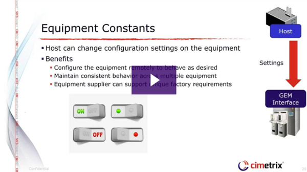
- Collect equipment parameters to drive preventative maintenance plans
Now that we understand GEM, we can explain the term “GEM Compliance”.
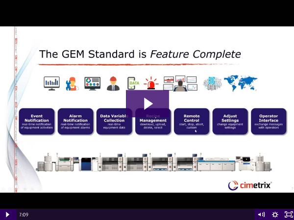
GEM Compliance is defined in the SEMI E30 GEM standard. To be “GEM Compliant” means your equipment implements a specific set of capabilities called “Fundamental GEM Requirements”. Your equipment may also implement optional features called “Additional Capabilities”. The SEMI E30 standard provides a list of all GEM features, as listed below.
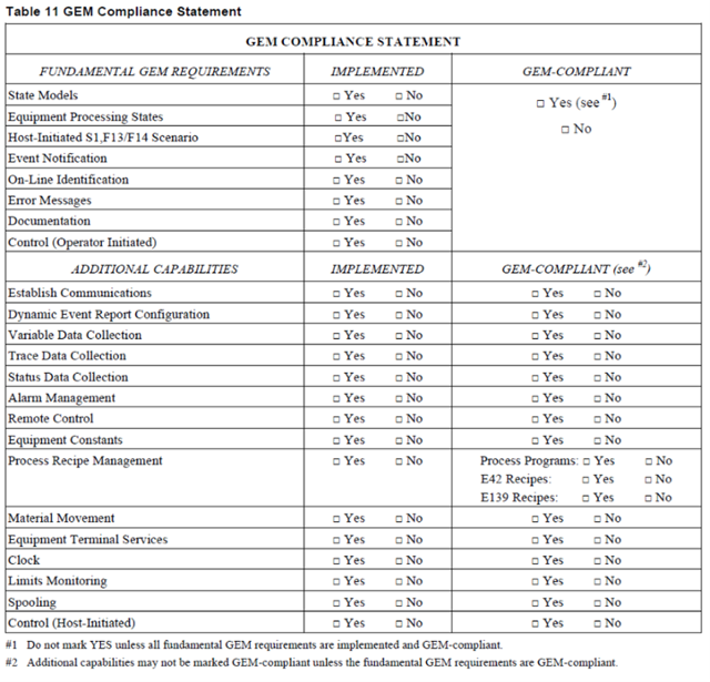
Per Table 11 Section 8.4.3. of the document "SEMI E30-0307E2"
So, how do you become “GEM Compliant”?
As mentioned above, to be GEM compliant, the equipment must implement the eight capabilities listed under Fundamental GEM Requirements. If one of the fundamental capabilities is not implemented, then you cannot say the equipment is GEM compliant. However, each capability listed under Additional Capabilities is optional. Implementing GEM also means implementing the other SEMI standards that GEM is based on including: E4 (SECS-I), E5 (SECS-II), E37(HSMS), E37.1 (HSMS-SS). In addition, depending on your industry, there may be additional standard to adhere to.
All-in-all, there are 100’s of standards pages filled with requirements and implementation information. Reading and implementing all the requirements defined in those standards may require extensive time. However, toolkits such as our CIMConnectTM product greatly reduce the number of people and time needed to implement a fully GEM compliant interface.
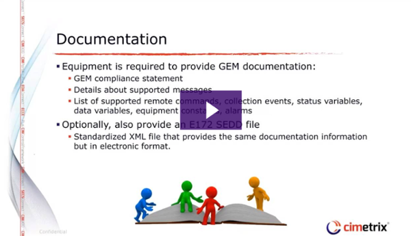
A simple GEM interface that only implements the Fundamental capabilities can be completed relatively quickly. However, a toolkit like CIMConnect enables a small team of one or two people to implement a fundamental interface in even less time. CIMConnect reduces time by implementing the GEM features that are common to all equipment, and providing API to implement the capabilities unique to your equipment. Toolkits also provide several utilities to help become GEM compliant. For example, one of the fundamental GEM requirements is to provide a GEM interface manual with each equipment. CIMConnect provides a template and a documentation builder to help create your manual. These tools reduce the time to create a GEM interface manual from weeks to hours. With products like CIMConnect, a more complex GEM interface can be implemented in just a couple weeks.
Whether you use CIMConnect or an in-house solution, the process for developing a GEM interface is roughly the same:
- Define and Document GEM interface
- Implement GEM interface
- Test GEM interface
- Customer accepts GEM interface
Defining and documenting the GEM interface of the equipment should be first because it helps to reduce feature creep, keep the project on course, and ensure the project is completed on time. Implementing the GEM interface is often the largest part of the process. Since no two equipment are alike, programming is required to customize the GEM interface for your equipment. It is common to test the GEM interface as each feature is implemented. Testing ensures your GEM implementation is compliant with the GEM standard and is defect free. Some use a completely manual testing process that can take weeks, but we recommend creating automated tests that can be built with our Cimetrix HostConnectTM product. Automated testing allows defects to be detected and fixed quickly; preventing unexpected development costs down the line. Once you believe your interface is free of defects, it’s time to get acceptance from your customer.
To ensure continued success, it is important for your GEM product supplier to provide training and on-going product support. Proper training and support from your GEM supplier allows you to provide continuous support to your customers.
Congratulations – you are on your way to being able to make your equipment “GEM Compliant”. You can successfully meet your customers’ requirements while keeping your team’s resources on their core competency.
 The Cimetrix Resource Center is a great tool for anyone who wants to learn more about industry standards including Equipment Connectivity and Control, data gathering, GEM (SECS/GEM), EDA/Interface A, and more. These standards are among the key enabling technologies for the Smart Manufacturing and Industry 4.0 global initiatives that are having a major impact on many industries. Manufacturers and their equipment suppliers must be able to connect equipment and other data sources, gather and analyze data in real time, and optimize production through a wide variety of applications. The free eBooks listed below provide in-depth coverage of the some of these concepts. They have been written by technical experts who have participated in and led the standards development processes for more than two decades.


 It's getting close to the end of 2018 and we thought it was a good time to look back over our year and think about the many things Cimetrix has done. We are really proud of our team, which spans the globe, their hard work and accomplishments throughout the year.
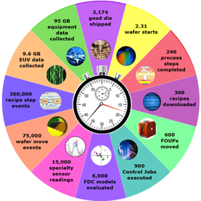
 You may not be responsible for running a gigafab anytime soon, but the SEMI standards used in this setting are no less applicable to any Smart Manufacturing environment. Give us a call if you’d like to know more about how these technologies can benefit your operations for many years to come.